Sealing ring with flow guiding blades in centrifugal pump

A technology of guide vanes and sealing rings, which is applied to the components, pumps, and pump components of pumping devices for elastic fluids, can solve problems such as processing and assembly difficulties, flow leakage, wear and other problems, and achieves reduction of maintenance costs, Good sealing performance, simple replacement effect

Inactive Publication Date: 2020-08-18
JIANGSU UNIV
View PDF7 Cites 2 Cited by
  • Summary
  • Abstract
  • Description
  • Claims
  • Application Information

AI Technical Summary

Problems solved by technology

However, a small gap will cause serious wear and a decrease in stability, and an overly complicated sealing structure is not conducive to production and assembly
[0004] At present, in order to solve the problem of flow leakage between the impeller and the volute of the centrifugal pump and the processing and assembly difficulties caused by the small gap and complex structure, a non-contact sealing structure that ensures good sealing performance under a large gap has been proposed. And setting texture on the sealing surface to prevent fluid leakage
However, the setting texture is destroyed under the long-term scouring action of particles and loses its original effect. Once the texture is damaged, a new mouth ring needs to be replaced. The body will be seized and the centrifugal pump will be damaged, which will increase the difficulty and cost of maintenance

Method used


Image

  • Sealing ring with flow guiding blades in centrifugal pump
  • Sealing ring with flow guiding blades in centrifugal pump
  • Sealing ring with flow guiding blades in centrifugal pump

Examples


Embodiment Construction

[0028] The present invention will be further described below in conjunction with the accompanying drawings and specific embodiments, but the protection scope of the present invention is not limited thereto.

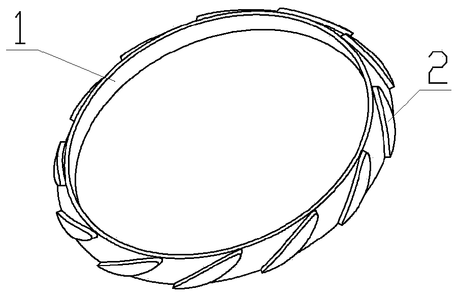
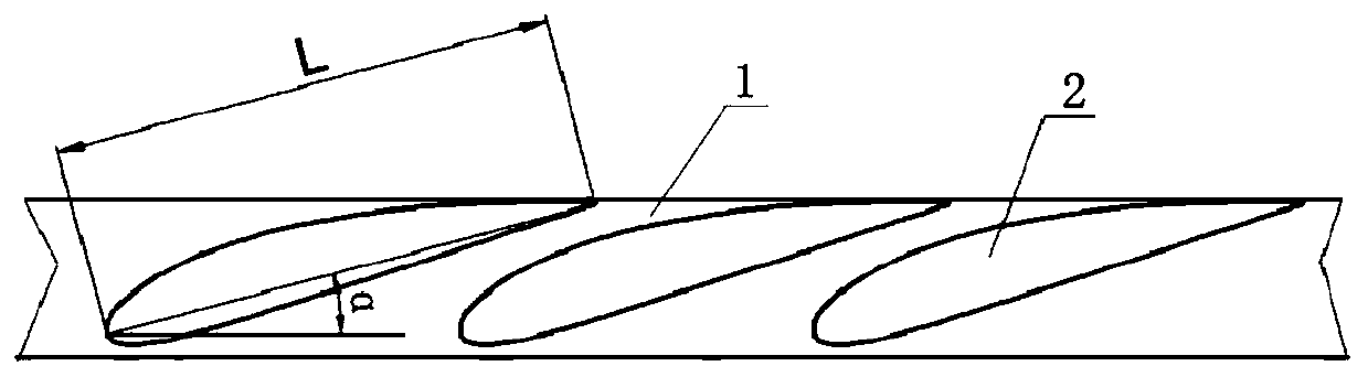
[0029] Such as figure 1 and Figure 5 As shown, the centrifugal pump of the present invention has a sealing ring of guide vanes, and the centrifugal pump includes a volute 3, an impeller 4 and a sealing ring 1, and the sealing ring 1 is located between the volute 3 and the impeller 4 Between, and the sealing ring 1 is installed on the impeller 4; the outer ring of the sealing ring 1 is uniformly distributed with a number of guide vanes 2 . The central axis of the sealing ring 1 and the central axis of the impeller 4 are collinear during installation. The cross section of the sealing ring 1 is trapezoidal, that is, the area of ​​one end surface of the sealing ring 1 is larger than the area of ​​the other end surface of the sealing ring 1 . Such as Figure 6 As shown, t...


PUM


Abstract

The invention provides a sealing ring with flow guiding blades in a centrifugal pump. The centrifugal pump comprises a volute, an impeller and the sealing ring, wherein the sealing ring is located between the volute and the impeller, and the sealing ring is mounted on the impeller; and the plurality of flow guiding blades are uniformly distributed on the outer ring of the sealing ring. The cross section of the sealing ring is trapezoidal, and an end face with large area of the sealing ring faces the impeller. The flow guiding blades are airfoil flow guiding blades, the plurality of flow guiding blades are uniformly distributed on the inclined surface of the sealing ring, and the tails of the airfoil flow guiding blades are flush with an end face with small area of the sealing ring. According to the sealing ring, the airfoil flow guiding blades are used to induce fluid to generate flow in the direction opposite to the leakage direction to prevent the fluid from flowing out of a gap between the volute and the impeller, thereby reducing the volume loss and improving the volumetric efficiency of the centrifugal pump.

Description

technical field [0001] The invention relates to the field of centrifugal pumps, in particular to a sealing ring with guide blades in the centrifugal pump. Background technique [0002] The centrifugal pump is a blade-type fluid machine. Its working principle is to drive the impeller to rotate through the prime mover to do work on the fluid, and convert the mechanical energy of the prime mover into the kinetic energy and pressure energy of the fluid, thereby realizing the transportation of the fluid. The flow leakage caused during the operation of the vane pump is inevitable, and the fluid leakage will cause the energy loss of the centrifugal pump. In general, the energy loss of centrifugal pumps is mainly divided into three types: flow loss, volume loss and disc friction loss. Among them, volume loss [0003] The loss refers to the flow loss caused by the fluid leakage between the impeller rotation and the casing, and the leakage amount is related to the pressure differenc...

Claims


Application Information

Patent Timeline
IPC IPC(8): F04D29/08
CPCF04D29/086
Inventor 丛小青李辉
Owner JIANGSU UNIV
Why Eureka
Try Eureka