
High-temperature resisting and high-pressure resisting injecting and extracting integrated double-layer hollow sucker rod

A hollow sucker rod, high-pressure technology, which is used in the production of fluids, drill pipes, and earthwork drilling, etc., can solve the problem that the vacuum double-layer hollow sucker rod cannot meet the high temperature process requirements, and save the time and structure of the pipe string. Reasonable design and the effect of filling technical gaps

Inactive Publication Date: 2013-12-25
刘铁
View PDF10 Cites 7 Cited by
  • Summary
  • Abstract
  • Description
  • Claims
  • Application Information

AI Technical Summary

Problems solved by technology

[0004] In order to overcome the deficiency that the existing steam injection oil production process needs to use two sets of pipe strings for gas injection and oil production, and the vacuum double-layer hollow sucker rod cannot meet the requirements of high-temperature technology, the present invention provides a high-temperature and high-pressure resistant integrated double-layer hollow sucker rod for injection and production. sucker rod

Method used


Image

  • High-temperature resisting and high-pressure resisting injecting and extracting integrated double-layer hollow sucker rod
  • High-temperature resisting and high-pressure resisting injecting and extracting integrated double-layer hollow sucker rod
  • High-temperature resisting and high-pressure resisting injecting and extracting integrated double-layer hollow sucker rod

Examples


Embodiment Construction

[0011] The present invention will be further described below in conjunction with drawings and embodiments. However, those skilled in the art should know that the present invention is not limited to the specific embodiments listed, as long as it conforms to the spirit of the present invention, it should be included in the protection scope of the present invention.

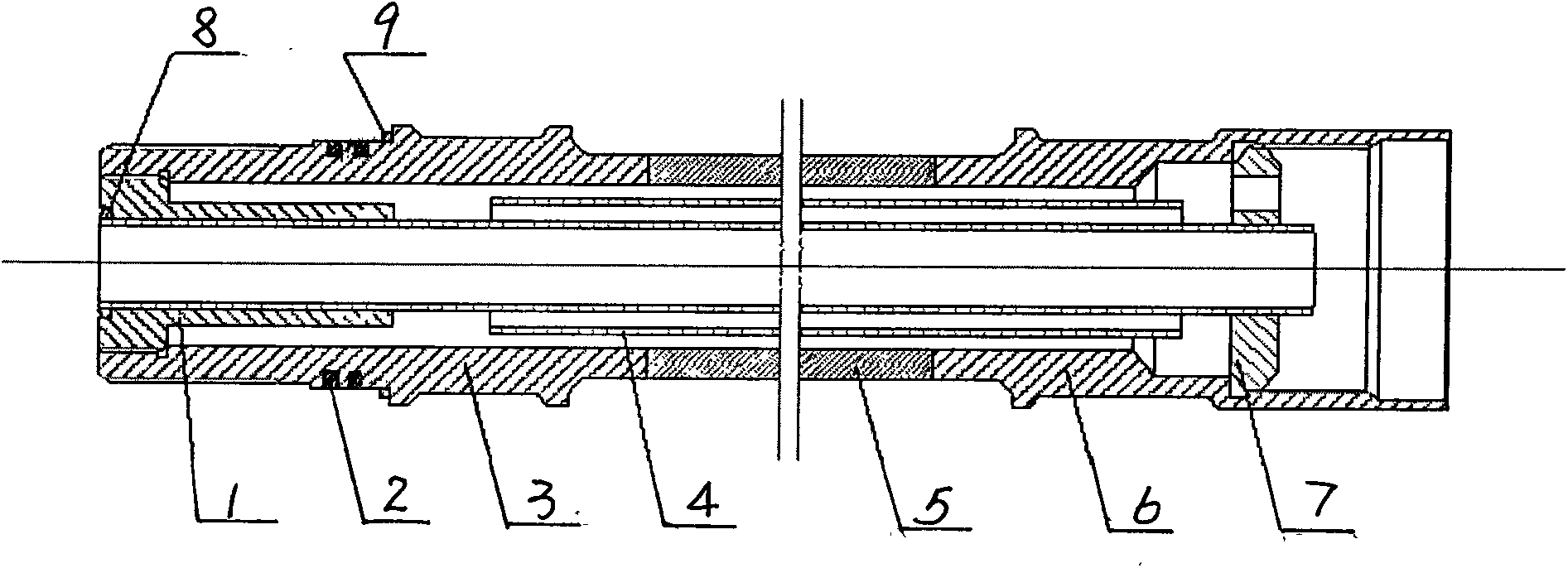
[0012] See attached figure 1 . The high-temperature and high-pressure resistant integrated double-layer hollow sucker rod for injection and production of the present invention includes a hollow rod and a center pipe 4 .

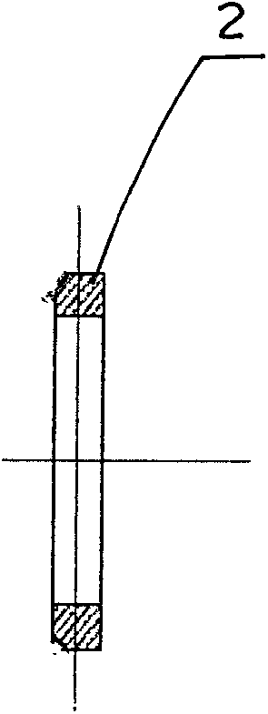
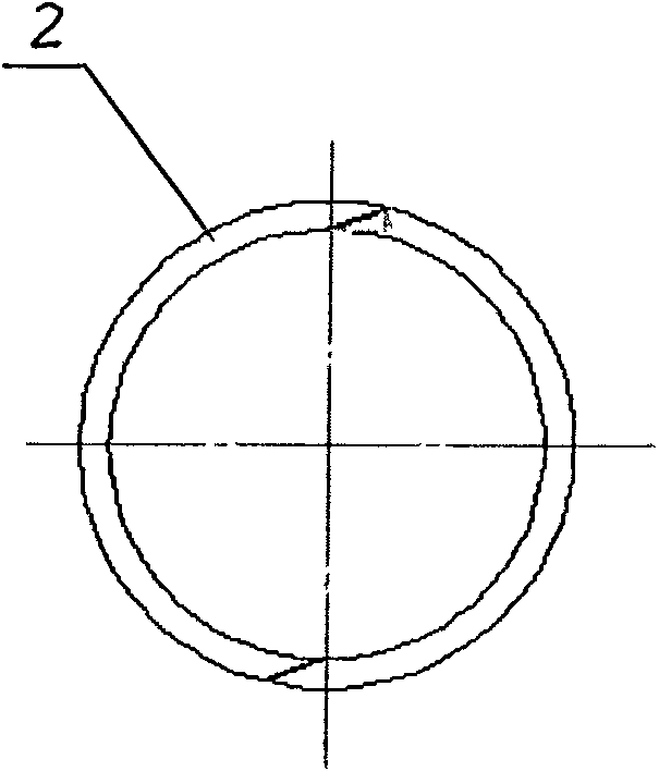
[0013] The upper joint 6, the rod body 5, and the lower joint 3 of the hollow rod are fixedly connected sequentially from top to bottom. A metal sealing ring I2 is installed in the annular groove at the upper end of the connection thread of the lower joint 3, and the metal sealing ring I2 is composed of two half rings, and the joint of the two half rings is a bevel joint (see attached figure 2 ...


PUM


Abstract

The invention relates to a high-temperature resisting and high-pressure resisting injecting and extracting integrated double-layer hollow sucker rod. In order to overcome the defects that the gas-injecting and oil-extracting two sets of tubular columns are required by the present steam injection oil extracting technology and the sealing effect cannot meet the requirement of a steam injection operation, an upper joint, a rod body and a lower joint of the hollow rod provided by the invention are fixedly connected in turn from up to down; a central pipe is located in the hollow rod; a space between an outer pipe and an inner pipe of the central pipe is hollow and annular; a metal sealing ring I is mounted in an annular slot at an upper end of a connecting thread of the lower joint; a metal sealing gasket is mounted on an upper end face of the connecting thread of the lower joint; and a metal sealing ring II is mounted between a lower end part of the inner pipe of the central pipe and a lower fixing sleeve. The high-temperature resisting and high-pressure resisting injecting and extracting integrated double-layer hollow sucker rod has the beneficial effects that the structure is reasonable; the metal sealing rings are adopted, so that the hollow sucker rod has high-temperature and high-pressure resisting properties and can meet the requirement of the steam injection oil extracting technology; the steam injection and oil extraction producing operation is finished by the next tubular column; and the technical blank of a super heavy oil steam-injecting oil-extracting integrated tubular column is filled up.

Description

technical field [0001] The invention relates to a vacuum double-layer hollow sucker rod, in particular to a high-temperature and high-pressure resistant integrated double-layer hollow sucker rod for injection and production, which is especially suitable for gas injection and oil production operations in super-heavy oil steam injection wells. Background technique [0002] With the continuous deepening of petroleum development, the proportion of super heavy oil and high pour point oil is increasing. At present, steam injection technology is mostly used for super heavy oil and high pour point oil. The steam injection process usually requires two sets of process strings for gas injection and production. First, the gas injection string is lowered for steam injection operation. After the gas injection, the gas injection string is lifted out of the wellbore, and then the gas injection string is lowered for oil recovery and production operations. Since the temperature of the injecte...

Claims


Application Information

Patent Timeline
IPC IPC(8): E21B17/18E21B43/24
Inventor 刘铁武雅黎沈涛杨伟
Owner 刘铁
Learn More