
Methods for controlling iron via magnetite formation in hydrometallurgical processes

a technology of magnetite and hydrometallurgical process, which is applied in the direction of process efficiency improvement, material recovery, etc., can solve the problems of high reagent cost, water consumption, final waste impoundment, and inability to treat/remove soluble iron from hydromet circuits using traditional methods, and the cost of oxidation is generally prohibitiv

Active Publication Date: 2020-06-23
F L SMIDTH & CO AS
View PDF3 Cites 0 Cited by
  • Summary
  • Abstract
  • Description
  • Claims
  • Application Information

AI Technical Summary

Benefits of technology

[0009]It is, therefore, an object of some embodiments of the present invention, to provide an improved hydrometallurgical process which may be adequately configured to selectively leach zinc, magnesium, and / or manganese (e.g., from other metals such as copper) both fully and rapidly, in a stepwise process, without limitation.
[0010]It is a further object of some embodiments of the present invention, to provide an improved hydrometallurgical process which may provide a cost effective iron removal process with minimal copper losses and reduced tailings volume, without limitation.
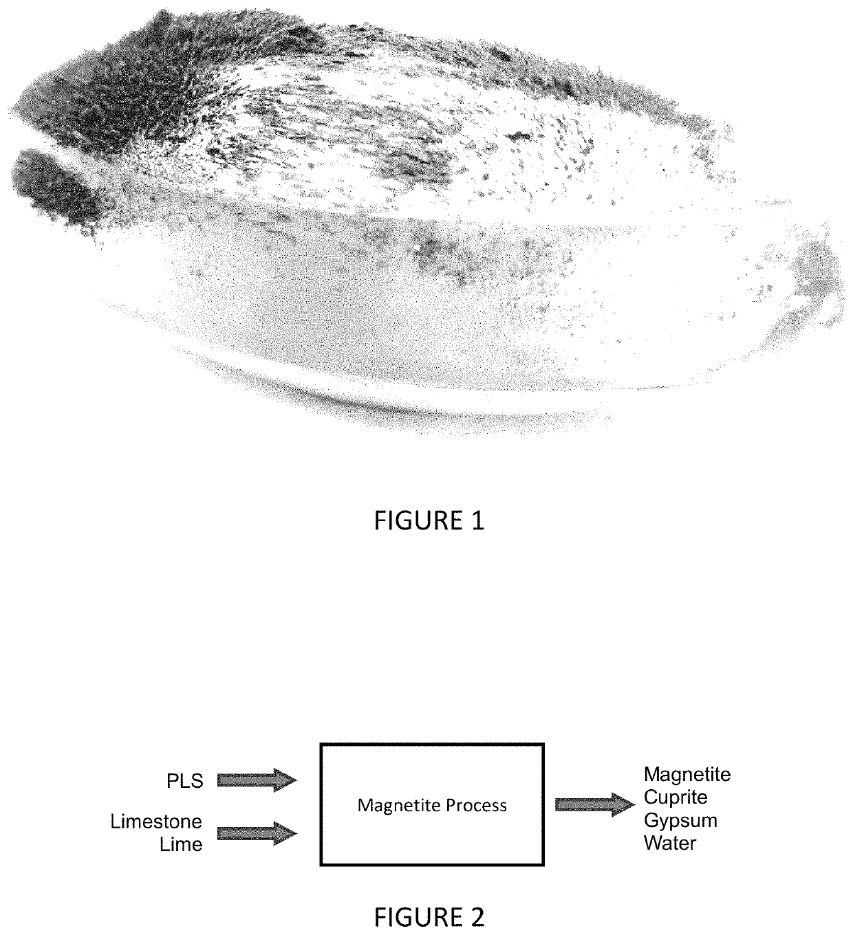
[0011]It is a further object of some embodiments of the present invention, to provide an improved hydrometallurgical process which involves the continuous production of and / or continuous formation of magnetite, in the presence of pay metals and which can be easily magnetically separated for iron removal and recovery, without limitation.
[0014]It is a further object of some embodiments of the present invention, to provide an improved hydrometallurgical process which, through stepwise leaching of a precipitate comprising magnetite solids and other metals, can allow pay metals (such as Zn and Cu) to be subsequently selectively and / or independently recovered from the precipitate (e.g., after iron precipitation) without limitation.
[0015]It is a further object of some embodiments of the present invention, to provide an improved hydrometallurgical process wherein magnetite can be separated through a combination of density and / or magnetic separation techniques to produce a saleable iron product, without limitation.
[0017]It is a further object of some embodiments of the present invention, to provide an improved hydrometallurgical process wherein little more than gypsum is sent to tails, and metal losses are mitigated, without limitation.

Problems solved by technology

This is because large volumes of waste can be generated through precipitation steps, at the further expense of high reagent costs, water consumption, and final waste impoundment.
While tenable for heap leach operations (due to the small quantities of iron in such heap leach operations), the amount of iron that can be generated during chalcopyrite leaching, zinc leaching, and / or nickel laterite leaching can make it cost prohibitive to treat / remove soluble iron from a hydromet circuit using traditional methods.
In particular, iron(II) (i.e., Fe2+) can substantially build up in chalcopyrite leach circuits and heap leach circuits, since raffinate-recycle streams coming from solvent extraction / electrowinning (SX / EW) circuits aren't efficiently configured to handle or remove excess residual iron economically.
Accordingly, a costly oxidation step would generally be required prior to the precipitation of iron in such leaching circuits.
For nickel laterite leaching, buildup of iron(III) in solution may require very expensive, high temperature autoclave operations, and these high temperatures tend to drive reactions towards the formation of less desirable species such as basic iron sulfate and hematite.
With these conventional two-stage impurity removal processes, low-density / high-surface area ferric hydroxides are formed, which are typically difficult to settle and filter.
Moreover, with these conventional two-stage iron removal processes, metal values still in solution along with the precipitates are typically disposed of as tails and are rarely recovered.
Moreover, with these conventional two-stage iron removal processes, all copper present in post-iron precipitation treated liquors can be lost to tailings, and therefore, streams that are selected for iron removal, or that can be adequately treated for iron removal are limited (this is especially true for copper-leaching circuits).
The voluminous nature of the ferric hydroxide precipitates, high water entrainment, and significant copper losses make iron removal a costly endeavor from both an economic and environmental perspective.
Moreover, with conventional iron-removal processing, large tailings impoundments are typically necessary and with the added disadvantage of significant water inventory trapped as hydrated iron species.
In short, conventional iron removal processes promote the formation of iron hydroxides that filter poorly, upset flowsheet water balance, co-precipitate with copper, lead to metal value losses, and fail to provide desirable iron byproducts.

Method used


Image

  • Methods for controlling iron via magnetite formation in hydrometallurgical processes
  • Methods for controlling iron via magnetite formation in hydrometallurgical processes
  • Methods for controlling iron via magnetite formation in hydrometallurgical processes

Examples


example

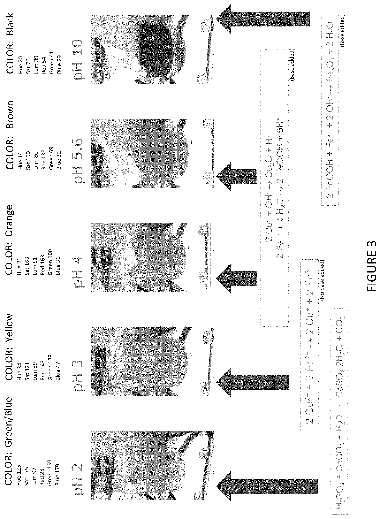
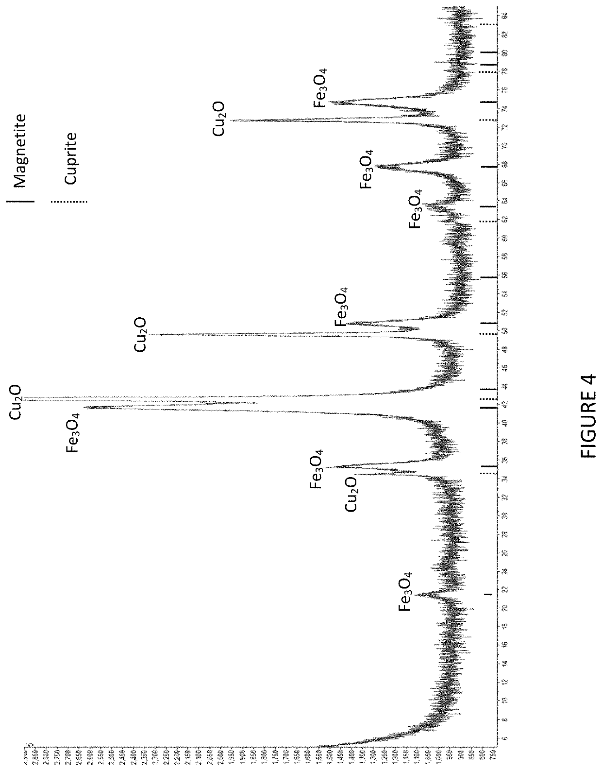
[0044]An example of magnetite processing according to a particular embodiment of the invention follows. The purpose of the test was to produce magnetite and cuprite as solid products from synthetic hydrometallurgical liquor.

[0045]The experiment was conducted by providing a solution of 5.2 g L−1 Cu and 8 g L−1 Fe(II) and pH 2.8. The solution was placed in a magnetically-stirred beaker. The pH was adjusted step-wise, over a thirty minute period, with addition of sodium carbonate, to reach a final pH of 9.9. The system temperature was gradually increased from ambient (20° C.) to reach 50° C. after 20 minutes, and then allowed to gradually fall back to ambient temperature (20° C.) for the remainder of the experiment.

[0046]The results of the experiment were as follows. The iron and copper were completely removed from solution to form a dense, black precipitate. Analysis of the final liquor by ICP-AES indicated that copper and iron, if present, were below detection levels (approximately l...


PUM

PropertyMeasurementUnit
molar ratioaaaaaaaaaa
temperatureaaaaaaaaaa

Abstract

A method of controlling iron in a hydrometallurgical process is disclosed. The method may comprise the steps of: leaching (14, 114) a feed slurry (2, 102); forming a pregnant leach solution (12a, 12b; 112a, 112b); removing a first leach residue (18, 118) from the pregnant leach solution (12a, 12b); and sending a portion (12b, 112b) of the pregnant leach solution (12a, 12b) and / or raffinate (22, 122) produced therefrom, to an iron removal process (34, 134). According to some preferred embodiments, the iron removal process (34, 134) may comprise the steps of: sequentially processing the pregnant leach solution (12a, 12b) and / or raffinate (22, 122) produced therefrom in a first reactor (R1) a second reactor (R2), and a third reactor (R3); maintaining a pH level of the first reactor (R1) above 4, by virtue of the addition of a first base; maintaining a pH level of the second (R2) and / or third (R3) reactors above 8.5, by virtue of a second base; and forming solids (46) comprising magnetite (68). The method may further comprise the steps of performing a solid liquid separation step (36) after the iron removal process (34, 134); and performing a magnetic separation step (64) to remove magnetite (68) from said solids comprising magnetite (68), without limitation. A system for performing the method is also disclosed.

Description

REFERENCE TO RELATED APPLICATIONS[0001]This application is a U.S. National Stage entry of PCT / IB2017 / 057553 filed 30 Nov. 2017, which claims priority to U.S. Provisional Patent Application No. 62 / 428,895 filed on Dec. 1, 2016.FIELD OF THE INVENTION[0002]Embodiments of the invention relate to equipment and processes concerning hydrometallurgical processing of slurries containing metals. In particular, embodiments of the invention relate to methods of precipitating iron in hydrometallurgical processes. More particularly, are methods of forming magnetite from leach liquors of copper concentrates, nickel laterites, zinc concentrates and acid mine drainage, as will be described in further detail hereinafter.BACKGROUND OF THE INVENTION[0003]Iron removal from process solutions may be considered to be the technical and economic crux of hydrometallurgical processing. This is because large volumes of waste can be generated through precipitation steps, at the further expense of high reagent co...

Claims


Application Information

Patent Timeline
Patent Type & Authority Patents(United States)
IPC IPC(8): C22B15/00C22B3/44C22B3/00C22B3/06
CPCC22B15/0089C22B3/06C22B3/44C22B23/0415C22B15/0067C22B23/0461Y02P10/234Y02P10/236Y02P10/20
Inventor CHAIKO, DAVID JOHNBACZEK, FRANKROCKS, SARA (SALLY)
Owner F L SMIDTH & CO AS
Learn More