
Smart drilling jar

a drilling jar and smart technology, applied in the field of drilling jars, can solve the problems of mechanical drilling jars, drilling jar fires immediately, and remains unsure of the integrity of tools, so as to improve the performance and effectiveness

Active Publication Date: 2020-06-09
SAUDI ARABIAN OIL CO
View PDF25 Cites 1 Cited by
  • Summary
  • Abstract
  • Description
  • Claims
  • Application Information

AI Technical Summary

Benefits of technology

Enhances the performance and safety of drilling operations by enabling controlled and efficient impact delivery, reducing the risk of unintended firing and equipment damage, and providing real-time diagnostics for improved operational efficiency and reduced downtime.

Problems solved by technology

However, doubts about the tool's integrity as well as the performance and efficiency of the drilling jar remain.
However, there are two disadvantages with a mechanical drilling jar.
The first disadvantage is that when the over pull / slack-off load exceeds the latch setting load, the drilling jar fires immediately.
This increase in load could be intentional or unintentional.
The resulting shock wave transmitted to the surface can damage the drilling rig hoisting equipment.
The second disadvantage is that the drilling jar may fire immediately as there is no time delay.
This flow causes the delay in functioning of the drilling jar.
Hydraulic drilling jars, however, do not have an internal latch, therefore they can easily transition from tension to compression.
Any load above the internal drag may cause the jar to fire contrary to a mechanical drilling jar, which requires exceeding the preset load.
Hydraulic drilling jars, however, have some limitations and restrictive operating procedures.
If the drilling jar fires while the drill string is supported in the slips, the resulting shock wave can cause the slips to jump out of the rotary table, releasing the drill string.
Picking up on the drill string again, may then cause the drilling jar to fire unexpectedly.
There is, however, a risk of the safety clamp being overlooked when running in the hole, preventing the drilling jar from functioning downhole.

Method used


Image

  • Smart drilling jar
  • Smart drilling jar
  • Smart drilling jar

Examples


Embodiment Construction

[0019]The methods and systems of the present disclosure may now be described more fully hereinafter with reference to the accompanying drawings in which embodiments are shown. The methods and systems of the present disclosure may be in many different forms and should not be construed as limited to the illustrated embodiments set forth herein; rather, these embodiments are provided so that this disclosure may be thorough and complete, and may fully convey its scope to those skilled in the art.

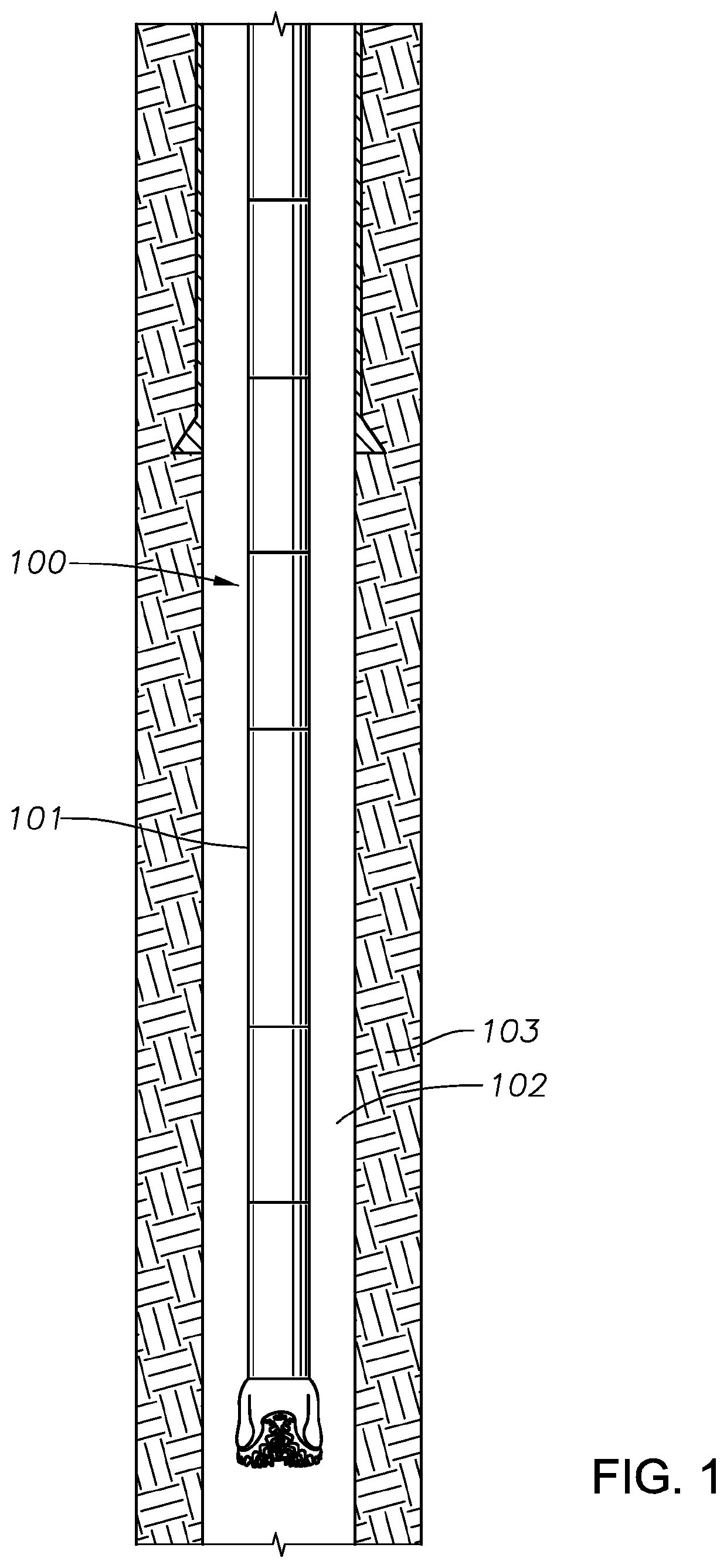
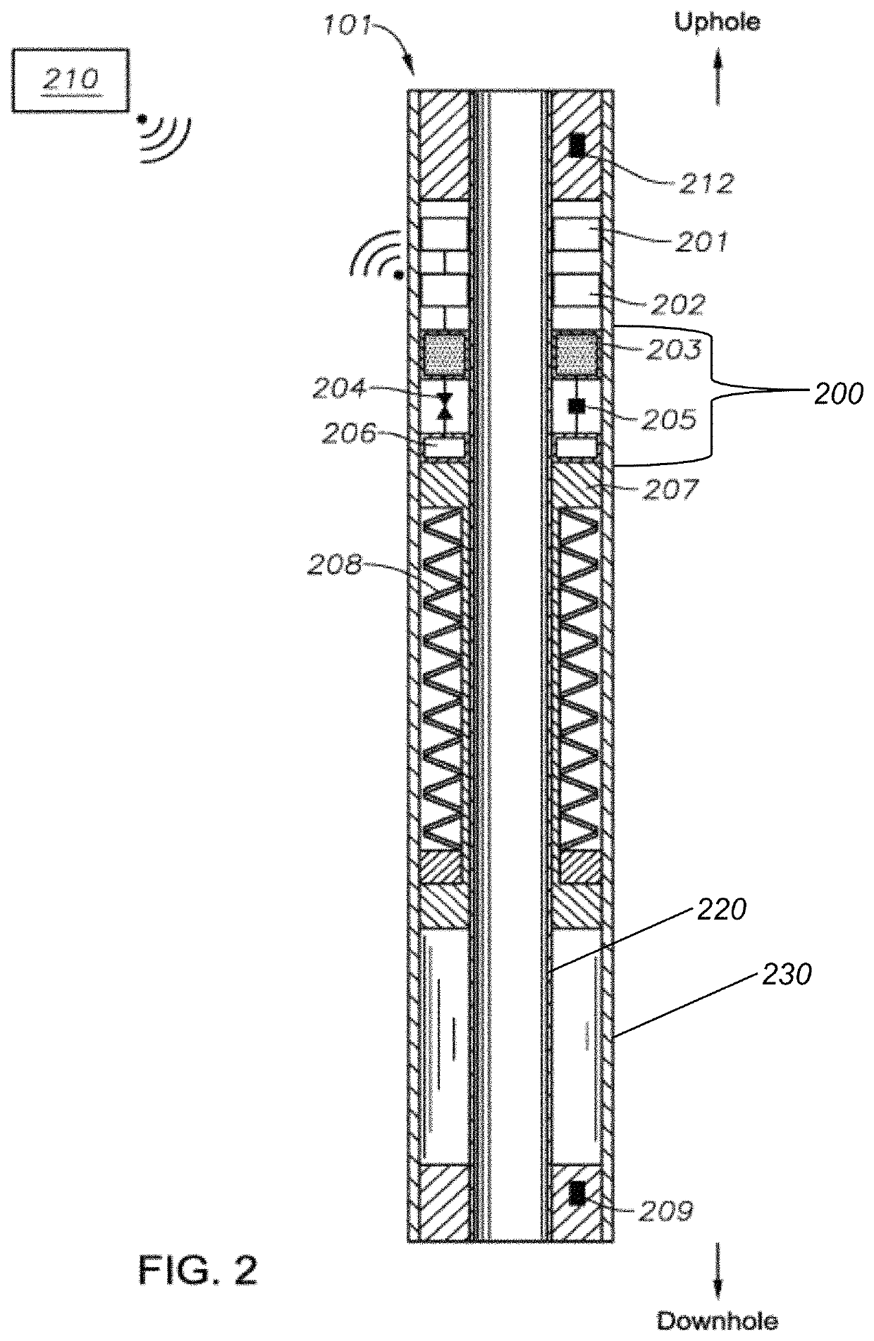
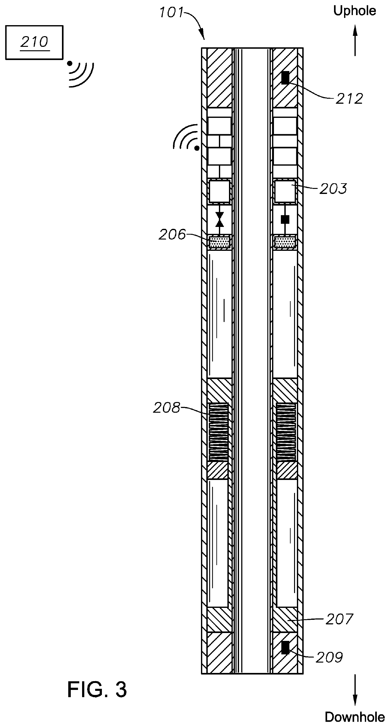
[0020]Turning now to the figures, FIG. 1 is a schematic of a bottom hole assembly (BHA) 100 including a drilling jar 101, according to one or more example embodiments. The drilling jar 101 may be positioned anywhere in the BHA 101. Although only one drilling jar 101 is illustrated in this figure, multiple drilling jars 101 can be distributed along the design of the drilling string or BHA 100. Additionally, the drilling jar 101 can be modified and applied to any size of drilling string. Annular s...


PUM


Abstract

A drilling jar in an oil and gas drilling operation or fishing operation includes a control unit having one or more transceivers configured to communicate wirelessly with a surface control unit. The control unit is configured to receive an activation signal from the surface control unit, and cause to activate the drilling jar in response to the activation signal. The wireless transceivers may communicate using any wireless communication technology, including but not limited to Wi-Fi, Wi-Fi Direct, and BLE. A method for operating a drilling jar includes receiving, by a control unit comprising one or more transceivers configured to communicate wirelessly with a surface control unit, an activation signal from the surface control unit, and causing to activate the drilling jar in response to the activation signal.

Description

BACKGROUNDField[0001]Embodiments of the present disclosure generally relate to drilling jars for use in oil and gas wells, and more specifically to a smart drilling jar.Description of Related ArtBACKGROUND[0002]A drilling jar is a tool added to the bottom hole assembly (BHA) with an objective to provide powerful downward and / or upward impact during a stuck pipe incident. Its main application is to free a stuck pipe in a well. The need to maximize the efficiency of drilling jars drives the oil and gas industry to develop and improve drilling jar mechanisms in order to be able to deliver an efficient system and jarring up and / or down for a longer period of time. However, doubts about the tool's integrity as well as the performance and efficiency of the drilling jar remain. There are mainly three types of drilling jars: mechanical, hydraulic and hydro-mechanical drilling jars.[0003]A mechanical drilling jar has a mechanism that is set to release at a specific preset load. To fire the d...

Claims


Application Information

Patent Timeline
Patent Type & Authority Patents(United States)
IPC IPC(8): E21B31/113E21B47/00E21B31/107
CPCE21B31/113E21B31/107E21B31/1135E21B47/00
Inventor COSTA DE OLIVEIRA, VICTOR CARLOSRIVAS MARTINEZ, MARIO AUGUSTOABOUELNAAJ, KHALED K.
Owner SAUDI ARABIAN OIL CO
Learn More