
Power management concept in DC distributed systems

a distributed system and power management technology, applied in the direction of transmission systems, dc source parallel operation, load balancing in the dc network, etc., can solve the problems of high cost, low flexibility, and difficulty in regulating the dc voltag

Active Publication Date: 2020-05-26
ARDA POWER
View PDF20 Cites 2 Cited by
  • Summary
  • Abstract
  • Description
  • Claims
  • Application Information

AI Technical Summary

Benefits of technology

The patent is about a system where multiple components work together to regulate the voltage of a DC bus. Each component measures the voltage and reacts to it, but they don't know what the system is trying to achieve. This helps to make the system more stable and able to adjust to changes in voltage. The components can also be physically separate from each other and still work well together. Overall, this makes it easier to add or remove components from the system without needing to completely re-engineer or re-tune it.

Problems solved by technology

In power distributed systems where the different elements are distant from each other, the regulation of the DC voltage is challenging.
However, physical distances between elements used in the DC bus voltage regulation compromise the stability and reliability of the system.
Wired and wireless communication means are commonly used to achieve power and energy balance between the different elements at the expense of extra cost and low flexibility.
Also, aging and tolerances in sensors degrade highly the performance of the DC distributed system.In other cases, DC bus voltage changes, resulting from changes in the power balance, trigger reactions in multiple or all of the elements to balance the power and maintain the DC bus within a specified range of voltages.
In this case, the system stability is difficult to achieve and oscillations are common.
Furthermore, for these concepts it is not possible to incorporate a secondary function, such as energy management, on top of the power balancing.

Method used


Image

  • Power management concept in DC distributed systems
  • Power management concept in DC distributed systems
  • Power management concept in DC distributed systems

Examples


Embodiment Construction

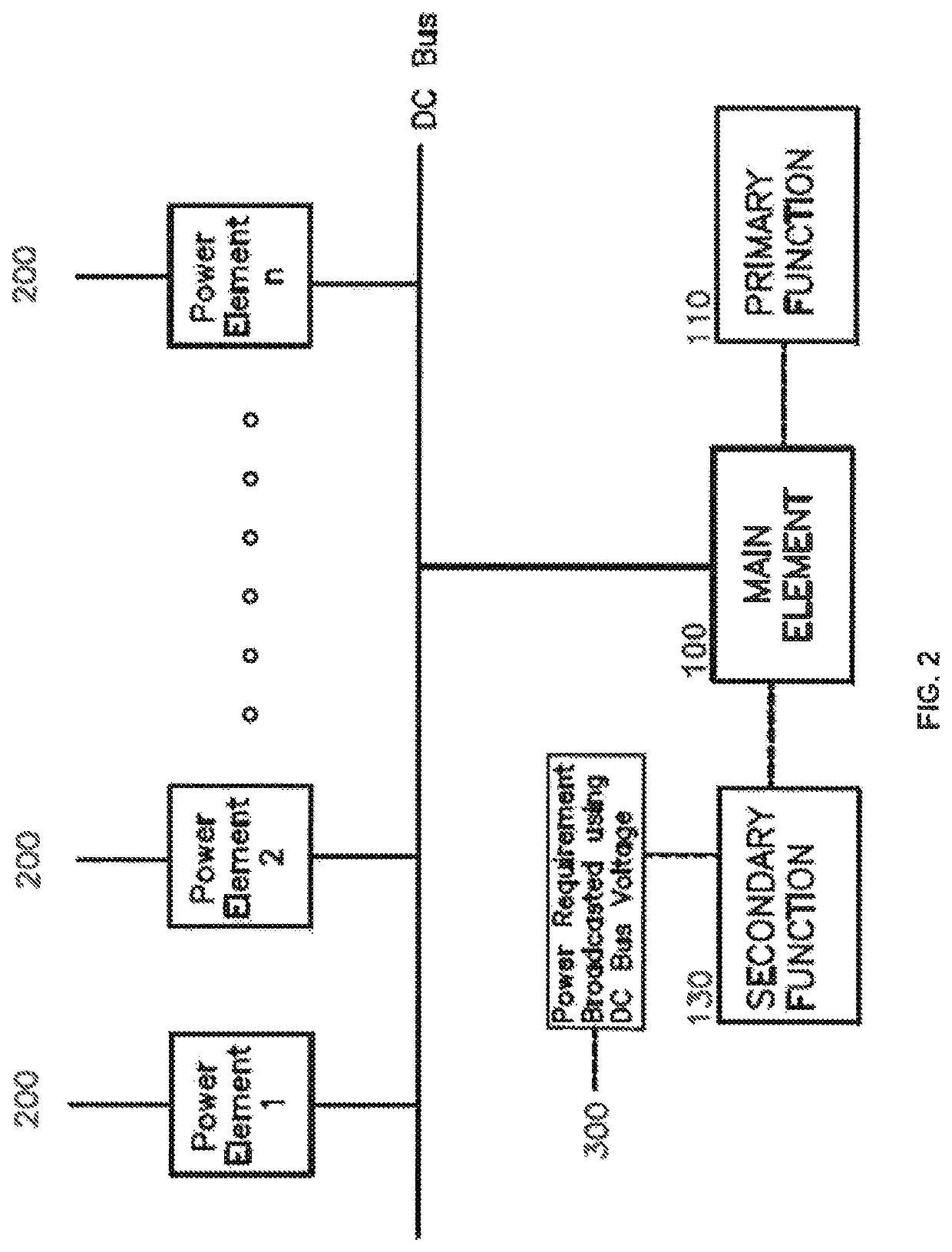
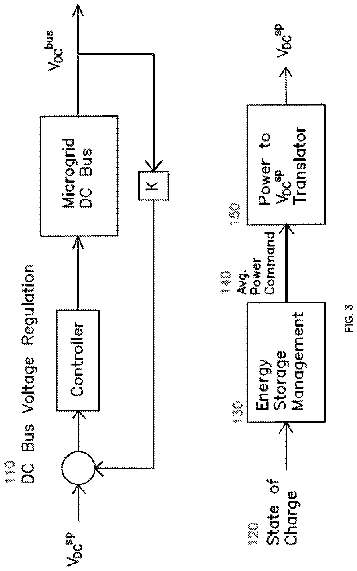
[0025]The invention presents a method to interconnect and control a DC power distribution system composed by multiple independent power elements including power generators and power consumers. The method enables achieving multiple levels of control using the DC bus voltage as the only mean of communication amongst the power elements. The primary level of control is the DC bus voltage regulation while the second level of control involves an independent variable that has slower dynamic response than the DC bus voltage. In other words, the changes in the independent variable controlled by the second level of control are considerably slower than the changes in DC bus voltage.

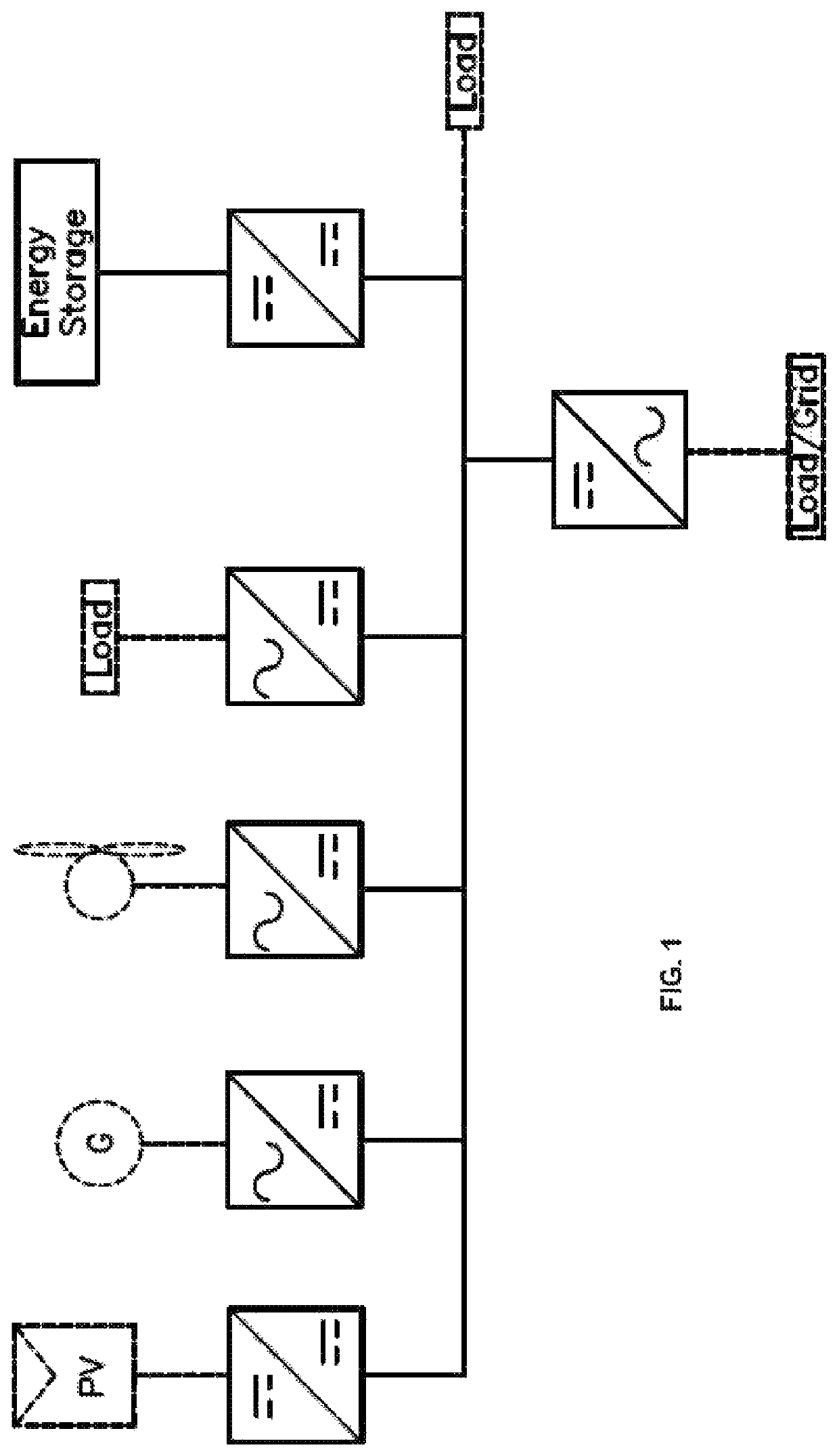
[0026]FIG. 1 illustrates a microgrid based on a DC distribution system. The DC distribution system uses a common DC bus to join multiple power elements and the continuous operation of the system depends on maintaining the DC bus voltage regulated within the normal operating range. Nevertheless, the different power e...


PUM


Abstract

A method includes the steps of providing a common DC bus to interconnect power elements to a DC distribution system using power converters. A first group of one or more of the elements (main element) is used to execute the primary function by automatically maintaining the DC bus voltage following a set point. The DC bus voltage set point is intentionally changed with slow dynamics according to a secondary function executed by the main element such that the average DC bus voltage regulated by the main element changes. A local logic is used on each of the power elements connected to the DC bus but different from the main element to modify their power generation or consumption as a result of changes in the measured average DC bus voltage such that they contribute to the fulfillment of the secondary level of control.

Description

CROSS-REFERENCE TO CO-PENDING APPLICATIONS[0001]This application is a continuation-in-part of U.S. patent application Ser. No. 14 / 858,856, filed Sep. 18, 2015, which application was a continuation-in-part of U.S. patent application Ser. No. 13 / 828,290 filed Mar. 14, 2013 and claims priority on U.S. Provisional Patent Application Ser. No. 62 / 182,788, filed Jun. 22, 2015.BACKGROUND OF THE INVENTION1. Field of the Invention[0002]The present invention is a method and system to interconnect and operate several conventional or alternative power generators, loads, and / or energy storage elements physically separated from each other in a DC distribution system.2. Prior Art[0003]DC power distribution systems are used to exchange power among multiple sources (mainly renewable energy resources), loads, and energy storage elements by connecting those elements to a common DC bus using power converters or direct connection in a concept generally called DC microgrid. A DC microgrid could be as simp...

Claims


Application Information

Patent Timeline
Patent Type & Authority Patents(United States)
IPC IPC(8): H02J1/12H02J1/14H02J3/38H02J7/00H02J1/10G05F1/12
CPCH02J1/102H02J1/14G05F1/12H02J3/381H02J7/0068H02J1/12H02J3/38Y10T307/352Y02E10/563H02J2300/24Y02E10/56
Inventor ZUBIETA, LUIS
Owner ARDA POWER
Learn More