Adhesive and structure, and adhesion method

a technology of adhesives and structures, applied in the field of adhesives, structures using adhesives, and adhesion methods using adhesives, can solve the problems of inability to ensure adequate adhesive strength, and achieve the effects of high strength, quick bonded, and adequate bond strength

Active Publication Date: 2020-05-12
MITSUBISHI HEAVY IND LTD +2
View PDF26 Cites 0 Cited by
  • Summary
  • Abstract
  • Description
  • Claims
  • Application Information

AI Technical Summary

Benefits of technology

[0028]The present invention allows members composed of a thermoplastic resin or a carbon fiber reinforced thermoplastic resin to be quickly bonded to each other without being damaged. The use of the adhesive of the present invention yields adequate bond strength, thereby providing a high-strength structure.

Problems solved by technology

However, for bonding between thermoplastic resins with the adhesive, the thermoplastic resins cannot be heated to the curing temperature of the thermosetting resin; thus, adequate adhesive strength cannot be ensured.

Method used


Image

  • Adhesive and structure, and adhesion method
  • Adhesive and structure, and adhesion method
  • Adhesive and structure, and adhesion method

Examples


example 1

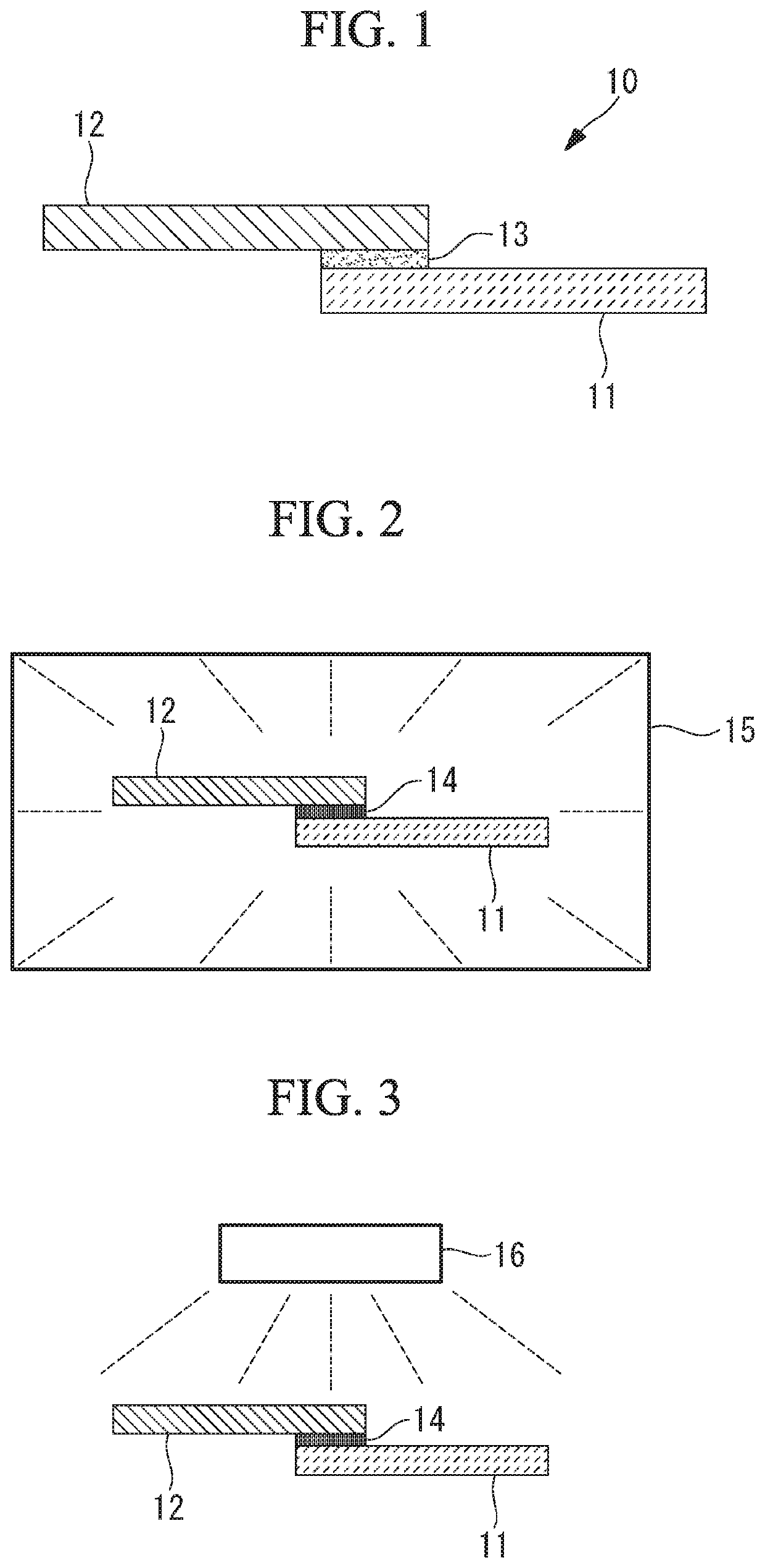
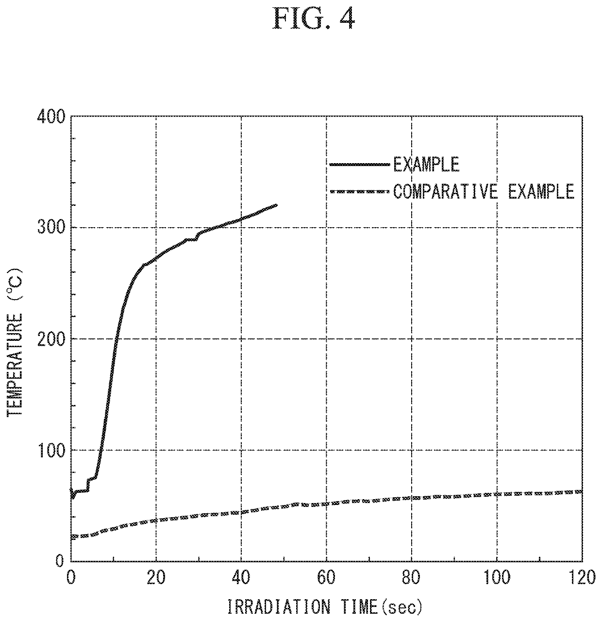
[0054]As a sample of this example, prepared was a PPS resin substrate (produced by TORAY industries, Inc., model number: A900, 10 mm high×10 mm wide×2 mm thick) with Pt nanocoils (solid coils with a diameter of 250 nm and a coil pitch of 3.2 μm) placed thereon. The substrate was placed on an electronic scale, and the Pt nanocoils were placed on the substrate. This measurement result showed that the value was below the lower measurement limit (0.1 mg). Accordingly, the amount of Pt nanocoils on the substrate was below 0.1 mg / cm2.

[0055]As a sample of a comparative example, prepared was a PPS resin (produced by TORAY industries, Inc., model number: A900) containing 60 wt % (1.3 g / cm3) of a NiZn-based ferrite (produced by JFE Chemical Corporation, model number: JN-350) mixed thereinto, molded on a substrate of 10 mm high×10 mm wide×2 mm thick. It should be noted that the ferrite material is a material traditionally known to exhibit high electromagnetic wave absorption efficiency.

[0056]E...

example 2

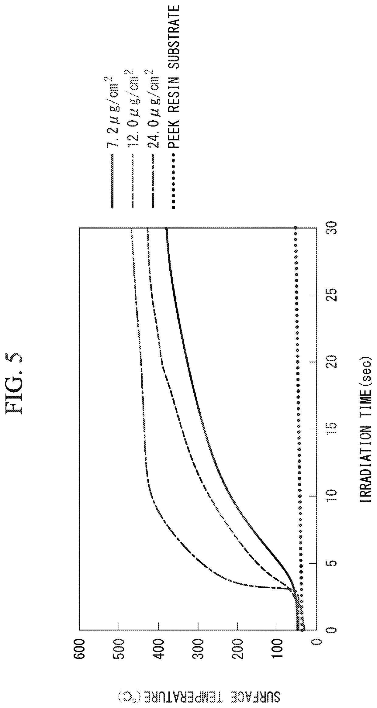
[0060]As a sample, prepared was a polyether ether ketone (=PEEK) resin substrate (produced by Victrex Japan, Inc., model number: 450G, 10 mm high×10 mm wide×3 mm thick) with Pt nanocoils (solid coils with a diameter of 250 nm and a coil pitch of 3.2 μm) placed thereon.

[0061]Here, the amounts of nano materials placed thereon were 7.2 μg / cm2, 12 μg / cm2, and 24 μg / cm2.

[0062]As a sample of a comparative example, the same polyetheretherketone resin substrate as in the aforementioned example was prepared and was irradiated with microwaves from above without Pt nanocoils placed thereon as in the aforementioned example. Variations in the temperature of the substrate surfaces with time were measured using an infrared thermography. FIG. 5 shows the results.

[0063]The surface temperature of the sample without a nano material placed thereon (the PEEK resin substrate) barely increased. In contrast, as the amount of nano material placed thereon increased, the surface temperature of the substrate i...


PUM

PropertyMeasurementUnit
frequencyaaaaaaaaaa
frequencyaaaaaaaaaa
sizeaaaaaaaaaa

Abstract

Provided is an adhesive that can provide quick bonding between thermoplastic resins and excellent bond strength, a structure having adhesion provided by the adhesive, and an adhesion method using the adhesive. The adhesive bonds a first member (11) containing a thermoplastic resin or a carbon fiber reinforced thermoplastic resin and a second member (12) containing the thermoplastic resin or the carbon fiber reinforced thermoplastic resin. The adhesive includes a thermoplastic resin as a main component containing a metal nano material that absorbs electromagnetic waves and generates heat.

Description

RELATED APPLICATIONS[0001]The present application is National Phase of International Application No. PCT / JP2016 / 053872 filed Feb. 9, 2016, and claims priority from Japanese Application No. 2015-023098, filed Feb. 9, 2015, the disclosure of which is hereby incorporated by reference herein in its entirety.TECHNICAL FIELD[0002]The present invention relates to an adhesive, a structure using the adhesive, and an adhesion method using the adhesive, particularly to an adhesive for bonding between thermoplastic resins.BACKGROUND ART[0003]Resins reinforced with carbon fibers (carbon fiber reinforced plastics) are materials having light weight, high strength, and high elasticity. Carbon fiber reinforced plastics are applied to aircraft members and wind turbine blades, for example. Examples of carbon fiber reinforced plastics include matrixes of thermosetting resins (carbon fiber reinforced thermosetting plastics: CFRPs) and matrixes of thermoplastic resins (carbon fiber reinforced thermoplast...

Claims


Application Information

Patent Timeline
Patent Type & Authority Patents(United States)
IPC IPC(8): C09J11/04B32B27/08B32B7/12B29C65/36C09J5/06B29C65/34B29C65/14B32B5/26C09J7/10B32B27/28C08K3/08C09J201/00B29C65/00B29C65/48B29C65/50C08K7/06C08K3/10B29K105/16
CPCB29C65/3468B29C65/3412B29C66/73921B29C65/481C09J5/06C09J11/04B29C65/148B29C65/5057B29C65/489B32B27/08B29C66/91951B29C66/1122C09J201/00B29C65/4815B29C65/1425B29C65/3676B29C66/43B32B27/288C09J7/10B29C65/3416B32B7/12B32B27/28B32B5/26B29C65/348B29C66/7212B32B2603/00B32B2260/021B29K2081/04B29C65/368C08K2003/0831C08K7/06C09J2471/006C09J2481/006C09J2205/102C09J2205/31C08K2201/005B29C65/3612B29C65/488B29C66/712B29K2067/006B32B2262/103B29K2071/00B29K2079/085B29C66/71B29K2307/04B32B2260/046C08K3/10B29K2077/00B32B2605/18B29K2105/162B29C65/3616B32B2262/106B29K2067/003B29C65/5014C08K3/08B29C66/91216B29C66/91221C09J2301/408C09J2301/416
Inventor TAKAYANAGI, TOSHIYUKIISHIKAWA, NAOMOTOHORIZONO, HIDEKIKAMIHARA, NOBUYUKIMURAOKA, MIKIOHAYASHI, HIROAKIYOSHIDA, OSAMUTSUJI, KOTARO
Owner MITSUBISHI HEAVY IND LTD
Why Eureka
Try Eureka