
Plasma processing apparatus

a technology of processing apparatus and plasma, which is applied in the direction of electrical apparatus, electric discharge tubes, basic electric elements, etc., can solve the problems of difficult temperature adjustment degraded adhesion between the focus ring and the mounting stage, and inefficient transfer of plasma heat input, etc., to achieve the effect of improving heat transfer efficiency between the mounting stage and the focus ring and reducing the temperature of the focus ring

Active Publication Date: 2020-04-14
TOKYO ELECTRON LTD
View PDF16 Cites 197 Cited by
  • Summary
  • Abstract
  • Description
  • Claims
  • Application Information

AI Technical Summary

Benefits of technology

The present invention can improve the transfer of heat between the mounting stage and the focus ring, and allow for variable control of the focus ring's temperature.

Problems solved by technology

When the heat transfer efficiency between the mounting stage and the focus ring is low, heat input from plasma may not be efficiently transferred from the focus ring to the mounting stage and temperature adjustment of the focus ring may be difficult.
That is, when the adhesive power of the heat transfer sheet is weak, the adhesion between the focus ring and the mounting stage may be degraded, and heat may not be efficiently transferred from the focus ring to the mounting stage.
Also, outgassing from the heat transfer sheet may occur.
Further, the heat transfer sheet may not be easily peeled off of the focus ring.
Accordingly, the temperature of the focus ring is fixed by the specification of the heat transfer sheet and the temperature of the focus ring cannot be variably controlled.

Method used


Image

  • Plasma processing apparatus
  • Plasma processing apparatus
  • Plasma processing apparatus

Examples


Embodiment Construction

[0019]In the following, embodiments of the present invention are described with reference to the accompanying drawings. Note that elements described below having substantially identical features are given the same reference symbols and overlapping descriptions thereof may be omitted.

[0020][Plasma Processing Apparatus / Substrate Supporting Apparatus]

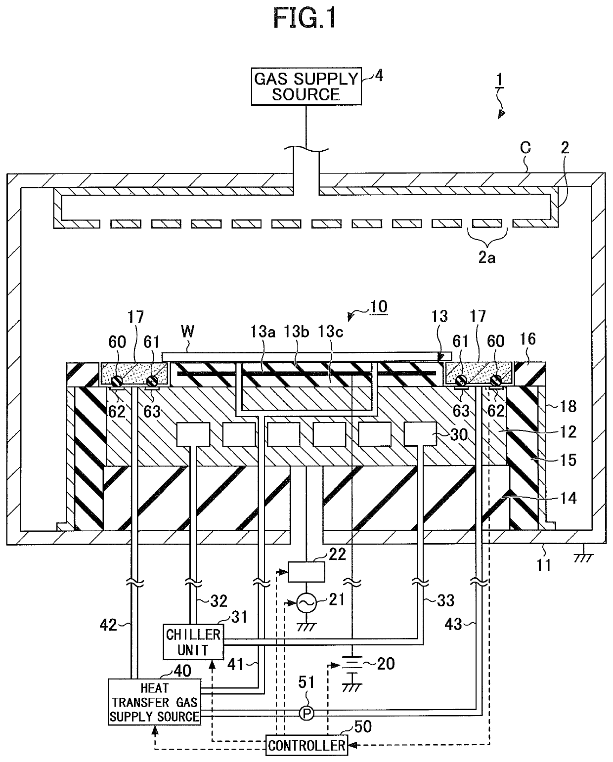
[0021]In the following, a plasma processing apparatus and a substrate supporting apparatus according to an embodiment of the present invention are described with reference to FIG. 1. FIG. 1 is a longitudinal cross-sectional view of a plasma processing apparatus according to an embodiment of the present invention. The plasma processing apparatus 1 illustrated in FIG. 1 includes a chamber (processing chamber) C that may be cylindrically-shaped, for example. The chamber C is grounded. A substrate supporting apparatus 10 is arranged on a lower wall of the chamber C. An upper electrode 2 is arranged at a ceiling portion of the chamber C to face...


PUM


Abstract

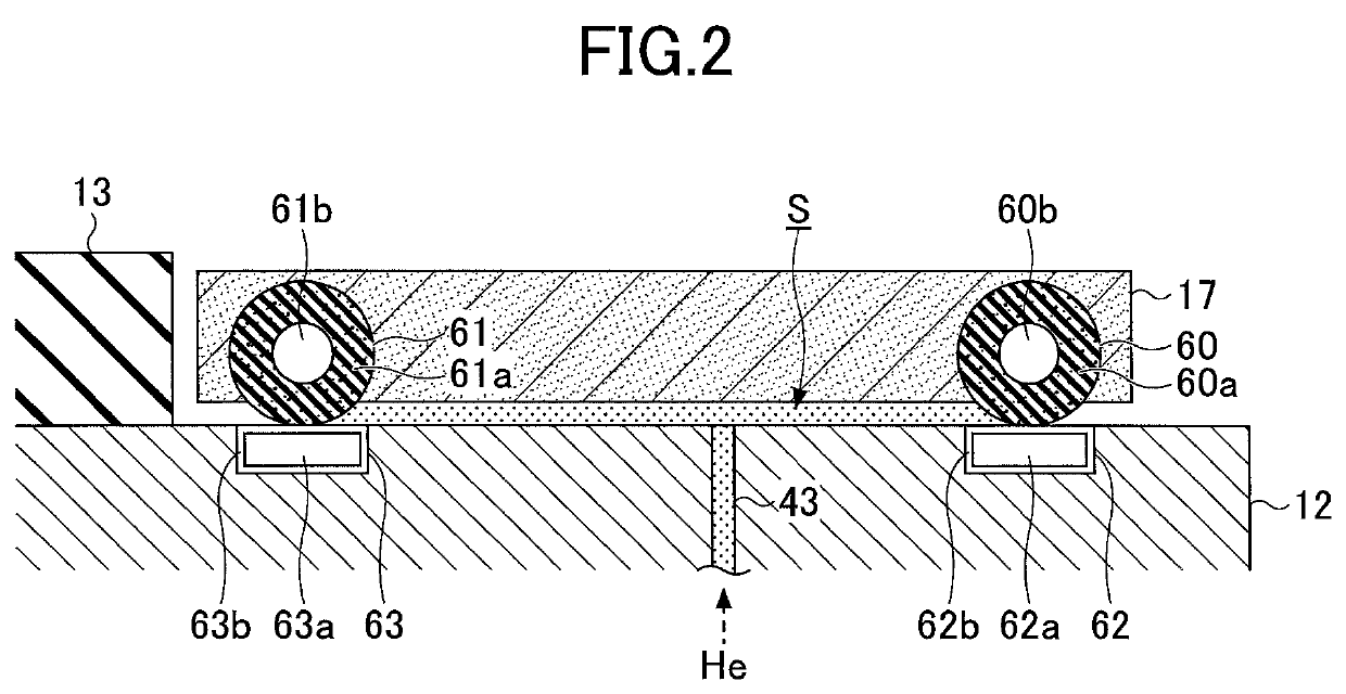
A plasma processing apparatus includes a mounting stage on which a substrate is mounted, a focus ring arranged around a periphery of the mounting stage, a plurality of magnetic members arranged at a surface of the focus ring and a surface of the mounting stage facing opposite each other, and a temperature adjustment unit configured to adjust a temperature of the focus ring by introducing a heat transfer gas between the surface of the focus ring and the surface of the mounting stage facing opposite each other.

Description

CROSS-REFERENCE TO RELATED APPLICATIONS[0001]This patent application is based upon and claims the benefit of priority of Japanese Patent Application No. 2013-171081 filed on Aug. 21, 2013, the entire contents of which are incorporated herein by reference.BACKGROUND OF THE INVENTION1. Field of the Invention[0002]The present invention generally relates to a plasma processing apparatus.2. Description of the Related Art[0003]In a semiconductor manufacturing process, plasma processes such as etching and film deposition are performed on a workpiece such as a semiconductor wafer (simply referred to as “wafer” hereinafter).[0004]Plasma processing apparatuses that subject a wafer to a plasma process include a mounting stage on which the wafer is mounted and a focus ring arranged on the mounting stage to surround the periphery of the wafer. The focus ring is configured to extend a plasma distribution region generated above the wafer to a region above the focus ring in order to secure plasma p...

Claims


Application Information

Patent Timeline
Patent Type & Authority Patents(United States)
IPC IPC(8): H01J37/32
CPCH01J37/32715H01J37/32642H01J37/32522H01J37/32669H01J37/32513H01J37/3266
Inventor NAGAYAMA, NOBUYUKISATOH, NAOYUKI
Owner TOKYO ELECTRON LTD
Learn More