
Channel estimation system and method thereof

a channel estimation and channel parameter technology, applied in the field of channel estimation system and method thereof, can solve the problems of increasing the hardware cost of the system, affecting the accuracy of channel estimation, so as to save estimation time, avoid joint estimation parameter error, and reduce the estimation error of channel parameters

Active Publication Date: 2020-03-17
WISTRON NEWEB
View PDF8 Cites 16 Cited by
  • Summary
  • Abstract
  • Description
  • Claims
  • Application Information

AI Technical Summary

Benefits of technology

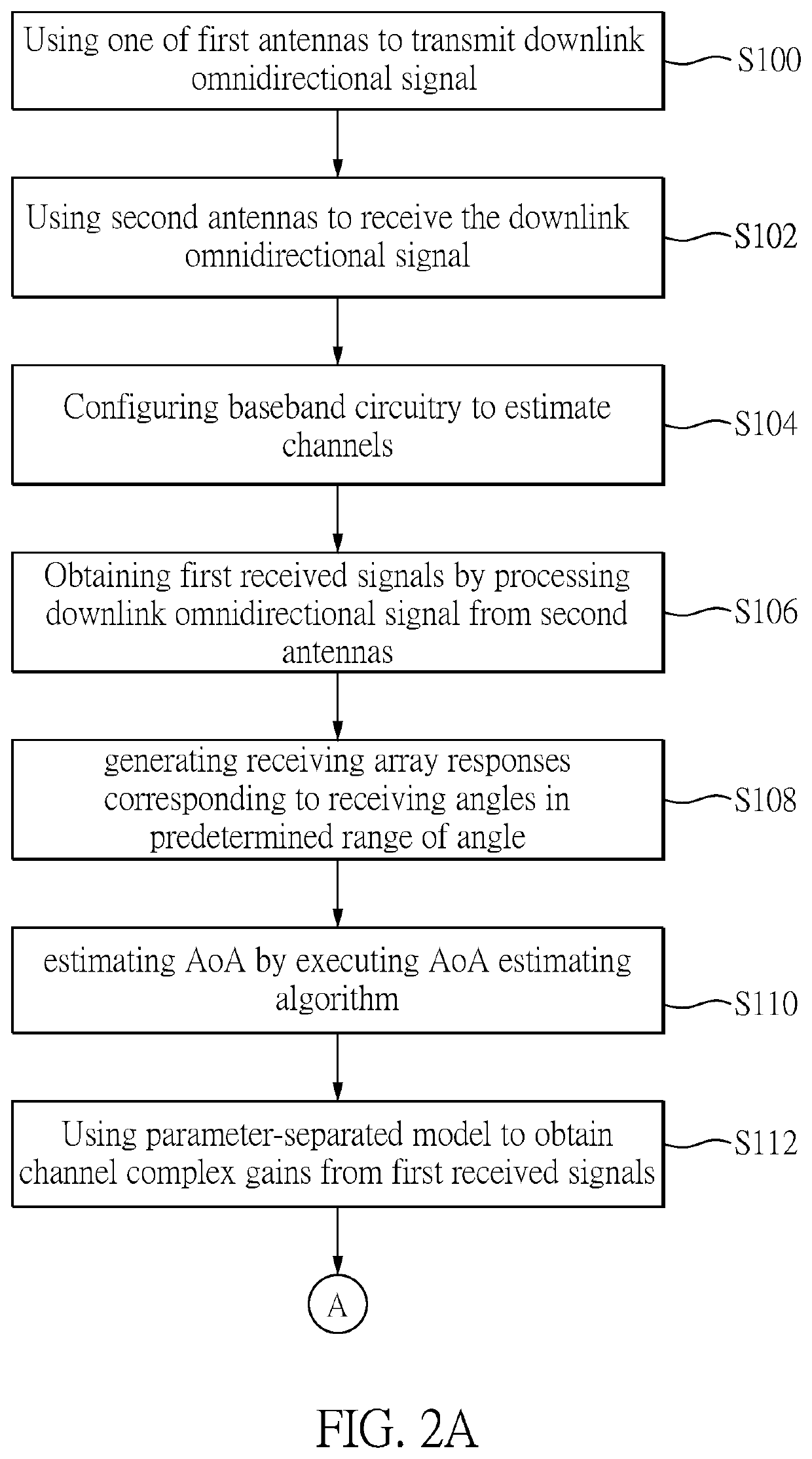
The present patent provides a method for estimating the parameters of a millimeter-wave channel using a mathematical model of separate parameters. The method separates each parameter into an independent estimation type, which helps avoid joint estimation parameter errors. The method also utilizes the reciprocal nature of uplink / downlink AoA and AoD of the millimeter-wave channel to save time of estimation and reduce the amount of observational data to be collected. Additionally, the method designs a Bayesian Estimator and calculates the observational value by using the back-end of the receiver to effectively reduce the feedback number of channel information and shorten the channel estimation time.

Problems solved by technology

However, the millimeter wave will withstand the high air loss effect at high frequencies (above 30 GHz), so that the transmission signal will have a serious loss in a short distance, and the ideal signal noise ratio cannot be obtained at the receiving end (Signal to noise ratio), here, the millimeter wave communication system needs to use beamforming technology (Beamforming) to obtain sufficient antenna gain to resist large air loss in high frequency, thereby effectively improving the signal noise at the receiving end.
However, it is not practical to deploy the same hardware architecture on the millimeter wave communication system.
A large number of RF chains and D / A converters will greatly increase the hardware cost of the system.
Moreover, the dimensions of the millimeter-wave channel matrix are much larger than in the previous communication systems, and the distribution of the channel paths is rather sparse due to the high air loss characteristics of the high-frequency electromagnetic waves, and thus objects that actually reflect and scatter the path of the channels are relatively rare.
These characteristics make the channel estimation method in the existing communication system no longer meet requirements for the actual application.
However, the existing scheme is not ideal in the training overhead and feedback numbers of channel estimation information, and therefore the process of estimating the channel will consume a certain amount of resources.

Method used


Image

  • Channel estimation system and method thereof
  • Channel estimation system and method thereof
  • Channel estimation system and method thereof

Examples


first embodiment

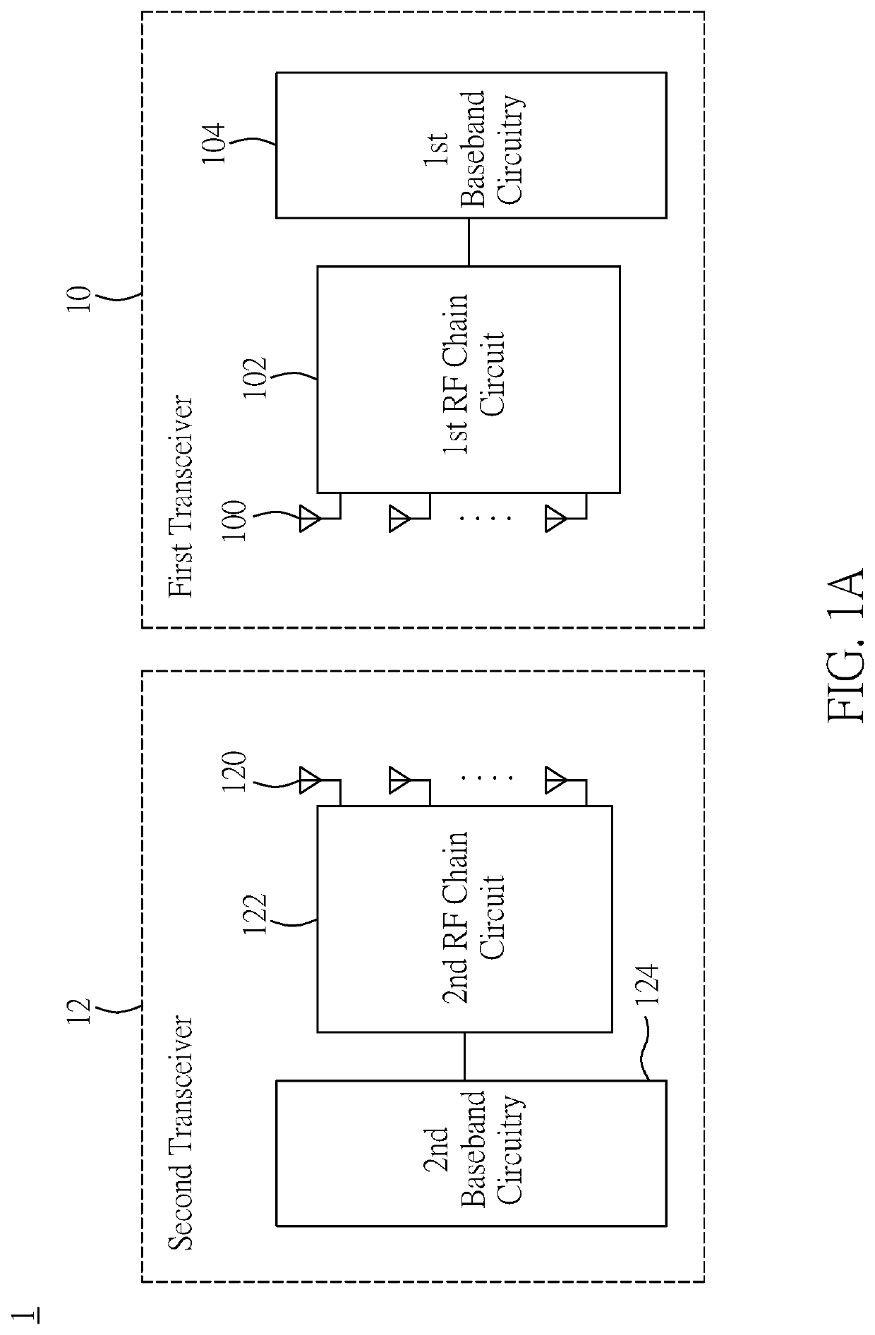
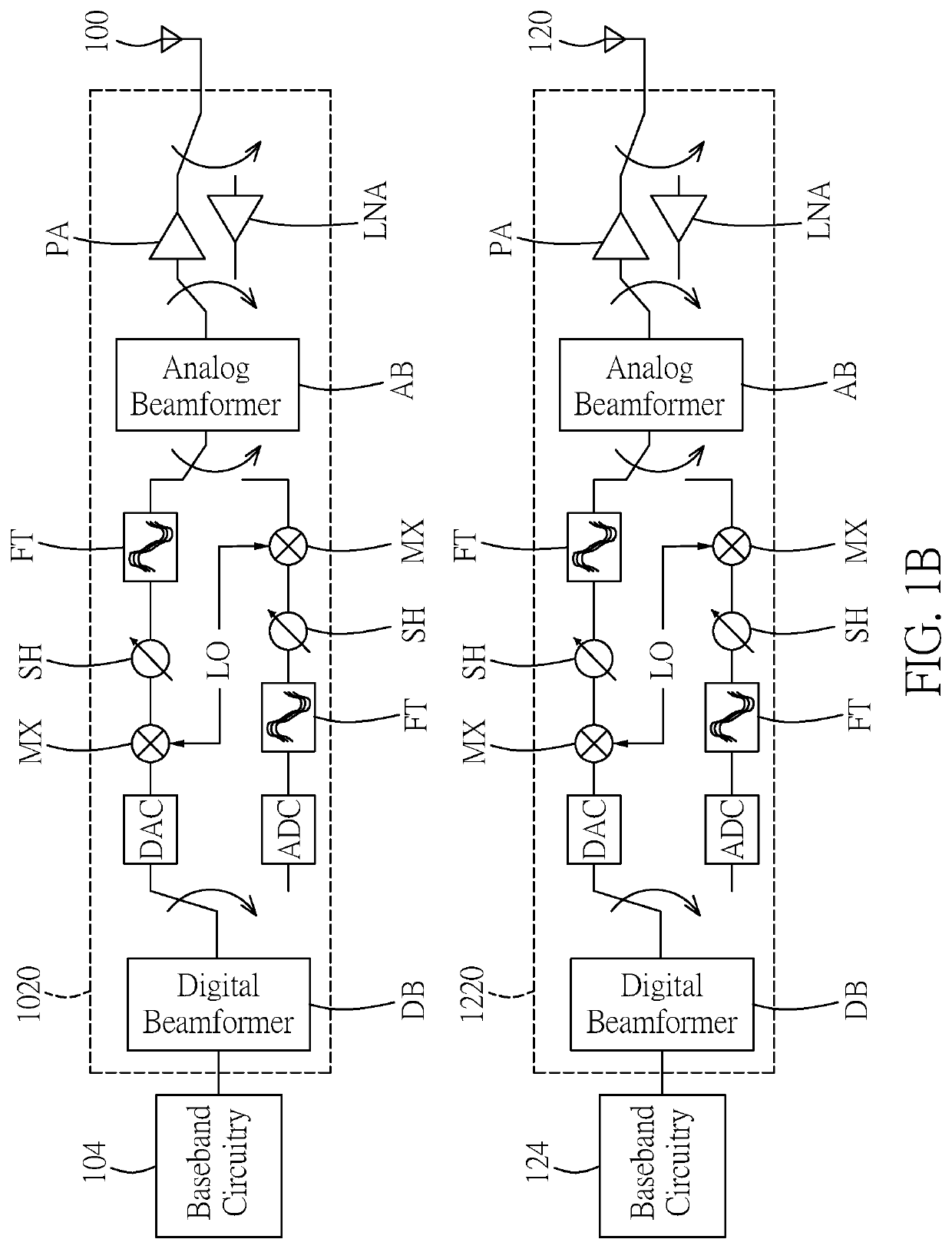
[0026]Reference is now made to FIGS. 1A and 1B, which are block diagrams of a channel estimation system and a RF chain circuit thereof according to a first embodiment of the present disclosure. As shown in FIG. 1A, the channel estimation system 1 includes a first transceiver 10 and a second transceiver 12. The first transceiver 10 includes a plurality of first antennas 100, a first RF chain circuit 102, and a first baseband circuit 104, and the first RF chain circuit 102 is coupled to the plurality of first antennas 100 and the first baseband circuit 104. Similarly, the second transceiver 12 includes a plurality of second antennas 120, a second RF chain circuit 122 and a second baseband circuitry 124, and the second RF chain circuit 122 is coupled to the plurality of second antennas 120 and the second baseband circuit 124.

[0027]The millimeter wave communication system utilizes a massive multiple input multiple output (massive MIMO) system, and a large number of antenna elements are ...

second embodiment

[0072]Reference is now made to FIG. 4, which is a block diagram of a RF chain circuit of a channel estimation system according to a second embodiment of the present disclosure.

[0073]As shown in FIG. 4, the second embodiment of the present disclosure provides a channel estimation system 2 including a first transceiver 20 and a second transceiver 22. The first transceiver 20 includes a plurality of first antennas 200, a first RF chain circuit 202, and a first baseband circuitry 204, and the first RF chain circuit 202 is coupled to the plurality of first antennas 200 and the first baseband circuitry 204. Similarly, the second transceiver 12 includes a plurality of second antennas 120, a second RF chain circuit 222 and a second baseband circuitry 224, and the second RF chain circuit 222 is coupled to the plurality of second antennas 220 and the second baseband circuitry 224.

[0074]In the fully digital architecture of the first embodiment, large numbers of antenna elements are provided at...

third embodiment

[0082]Simulations for the baseband end in the channel estimation system are performed, and the measure of the estimator's performance is measured by the mean square error between the estimated parameters and the actual channel parameters. Since Gaussian noise may exist between the signals transmitted in the channel, multiple repeated training beams are transmitted to collect the observation values to reduce the error, and the average observation value is obtained for eliminating noise. In the simulation, the number of observation beams is set to 15, 20, and 25 times respectively. The simulation results of the three-stage estimation channel parameter method in the present disclosure are respectively illustrated below.

[0083]Reference is now made to FIG. 5, which is a simulation result of estimation performance for the downlink AoA according to the present disclosure. In this example, the difference between the estimated AoA and the actual AoA for each signal-to-noise ratio is shown. T...


PUM


Abstract

A channel estimation system and method thereof is provided. By utilizing the nature of the millimeter-wave channel with sparse path, the channel estimation problem is transformed from estimating the entire channel matrix to estimating independent parameters of the millimeter-wave channel. These parameters are angle of arrival (AoA) and angle of departure (AoD), and complex gain of the channel paths.

Description

FIELD OF THE DISCLOSURE[0001]The present disclosure relates to a channel estimation system and method thereof, and more particularly to a channel estimation system and method transforming the channel estimation problem from estimating the entire channel matrix to estimating independent parameters of the millimeter-wave channel by using the nature of the millimeter-wave channel with sparse paths.BACKGROUND OF THE DISCLOSURE[0002]Today's communication systems are approaching the maximum threshold that can be used in terms of bandwidth size or data throughput. To further improve channel capacity, it is necessary to resort to higher frequency electromagnetic wave bands, which makes the millimeter-wave communication an important development direction for future mobile communication, because its large frequency band will bring more ideal channel capacity, which will make the transmission of large amounts of data feasible, and many communication specification, such as fifth generation mobi...

Claims


Application Information

Patent Timeline
Patent Type & Authority Patents(United States)
IPC IPC(8): H04L25/02H04B7/0413H04B7/06
CPCH04L25/021H04L25/0204H04B7/0617H04L25/0242H04B7/0413
Inventor LO, HSIN-YUANTSAI, SHANG-HOHUANG, SHOOU-HANNCHUANG, CHUN-HSIUNG
Owner WISTRON NEWEB
Learn More