Coin detection antenna and coin processing device

a coin processing device and coin detection technology, applied in the direction of resonant antennas, inductance without magnetic cores, instruments, etc., can solve the problem of not being able to detect upright coins, and achieve the effect of reliably blocking the magnetic field, reducing or preventing the structural complexity of the coin detection antenna, and more reliably detection

Active Publication Date: 2020-03-17
FUJI ELECTRIC CO LTD
View PDF2 Cites 0 Cited by
  • Summary
  • Abstract
  • Description
  • Claims
  • Application Information

AI Technical Summary

Benefits of technology

[0008]In the coin detection antenna according to the first aspect of the present invention, as described above, the width of the air core of the air core coil in the short-side direction is equal to or less than twice the thickness of the smallest coin having the smallest thickness of the coins to be detected. Thus, the width of the air core of the air core coil in the short-side direction can be made sufficiently small with respect to the thickness of the smallest coin, and thus an upright coin can reliably block a magnetic field even when the upright coin is located at a location corresponding to the air core of the air core coil. Consequently, even when the upright coin is located at the location corresponding to the air core of the air core coil, the upright coin can be detected.
[0010]In the aforementioned coin detection antenna according to the first aspect, a length of a linear portion of the air core coil in a direction in which the linear portion extends is preferably equal to or more than a diameter of the smallest coin having a smallest diameter of the coins to be detected. According to this structure, as compared with the case where the length of the linear portion of the air core coil in the direction in which the linear portion extends is less than the diameter of the smallest coin, the magnetic field can be more reliably blocked by the coins, and thus the coins can be more reliably detected.
[0011]In the aforementioned coin detection antenna according to the first aspect, the air core coil preferably includes a plurality of air core coils, and the plurality of air core coils is preferably disposed along short-side directions of air cores of the plurality of air core coils such that the air core coils in which current flow directions in adjacent portions are same as each other are adjacent to each other. Here, when the upright coin is located at a location corresponding to a gap between the adjacent air core coils, there are cases where the upright coin cannot be detected because the magnetic field cannot be sufficiently blocked by the coin, similarly to the case where the upright coin is located at a location corresponding to the air core of each of the air core coils. Therefore, as described above, the plurality of air core coils is disposed along the short-side direction of the air core such that the air core coils in which the current flow directions in the adjacent portions are the same as each other are adjacent to each other. Thus, the magnetic field can be generated to connect the air cores of the adjacent air core coils. Consequently, even when the upright coin is located at the location corresponding to the gap between the adjacent air core coils, the upright coin can reliably block the magnetic field generated to connect the air cores of the adjacent air core coils. Thus, even when the upright coin is located at the location corresponding to the gap between the adjacent air core coils, the upright coin can be detected. Furthermore, the air core coil includes the plurality of air core coils such that the coins can be detected in a wide range, and thus both the upright coin and the coin laid flat can be easily detected. In order to detect the coins in a wide range, it is only necessary to provide one substrate on which the plurality of air core coils is provided, and it is not necessary to provide a plurality of substrates on which the air core coils are provided, and thus the structural complexity of the coin detection antenna can be significantly reduced or prevented. Furthermore, the plurality of air core coils is disposed along the short-side direction of the air core such that generation of a dead space can be prevented as little as possible, and thus the size of the substrate can be reduced. Consequently, even when the plurality of air core coils is provided, the size of the coin detection antenna can be reduced.
[0012]In the aforementioned structure in which the air core coils in which the current flow directions in the adjacent portions are the same as each other are adjacent to each other, a size of a gap between the air core coils adjacent to each other preferably allows generation of a magnetic field that connects air cores of the air core coils adjacent to each other. According to this structure, even when the upright coin is located at the location corresponding to the gap between the adjacent air core coils, the upright coin can be more reliably detected.
[0013]In this case, the size of the gap between the air core coils adjacent to each other is preferably equal to or less than a width of each of the air cores of the plurality of air core coils in the short-side directions. According to this structure, the magnetic field that connects the air cores of the adjacent air core coils can be more reliably generated.
[0014]In the aforementioned structure in which the air core coils in which the current flow directions in the adjacent portions are the same as each other are adjacent to each other, the plurality of air core coils is preferably connected in series. According to this structure, the air core coils can be connected to each other with a simple structure as compared with the case where the plurality of air core coils is connected in parallel.

Problems solved by technology

In the air core coil as disclosed in Japanese Patent Laid-Open No. 2017-058861, when an upright coin is located at a location corresponding to the air core of the air core coil, there are cases where the upright coin cannot be detected because a magnetic field cannot be sufficiently blocked by the coin.

Method used


Image

  • Coin detection antenna and coin processing device
  • Coin detection antenna and coin processing device
  • Coin detection antenna and coin processing device

Examples


first embodiment

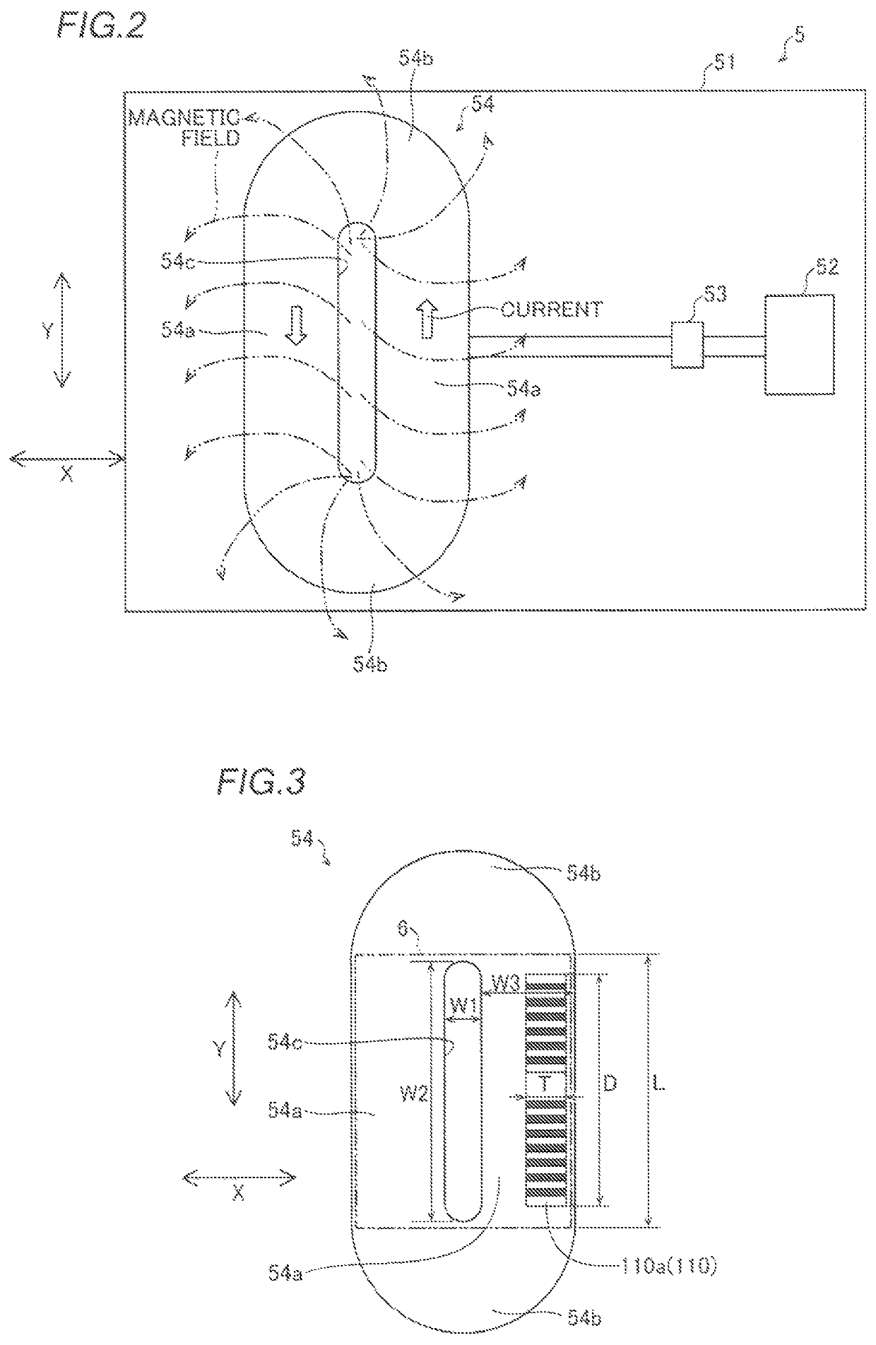
[0024]The structure of a coin processing device (change machine) 100 according to a first embodiment is now described with reference to FIGS. 1 to 3.

Structure of Coin Processing Device

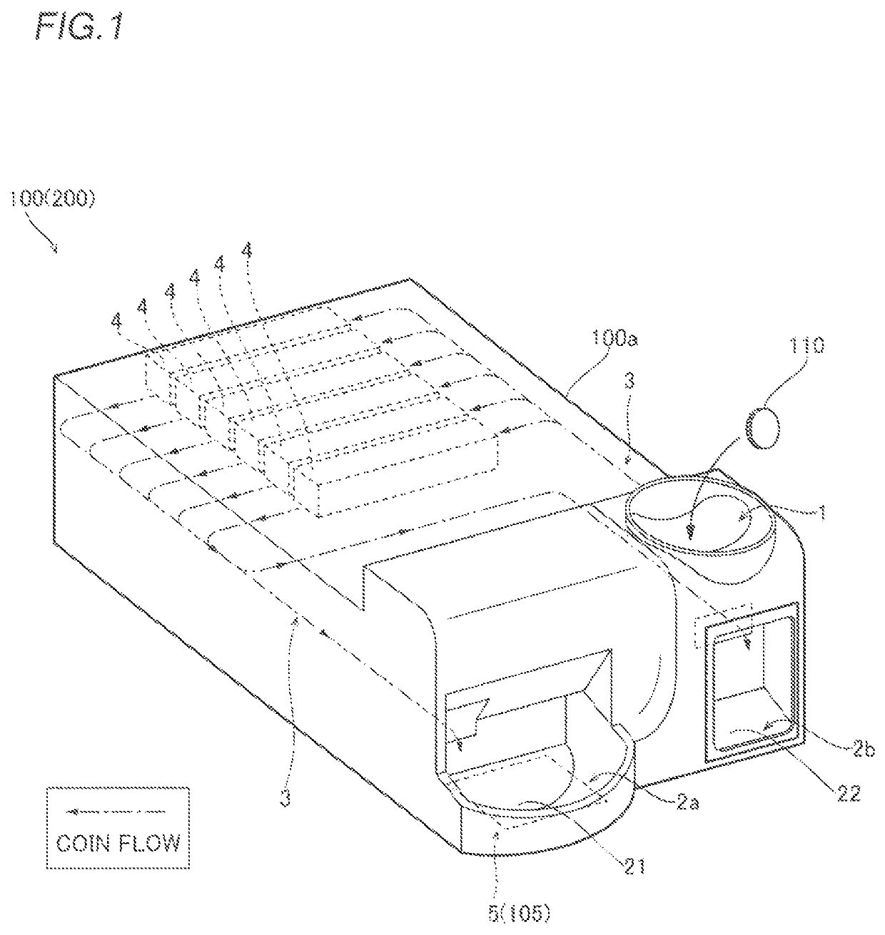
[0025]As shown in FIG. 1, the coin processing device 100 is a device that performs input and output of coins 110. The coin processing device 100 constitutes a part of a POS system including a POS (point of sales) register, a bill processing device, a coin roll container, etc., for example. The coin processing device 100 is installed in a store such as a supermarket or a convenience store, for example.

[0026]The coin processing device 100 includes an insertion slot 1, two discharge ports 2a and 2b, a coin transfer unit 3, and coin containers 4. The insertion slot 1 is an entrance through which the coins 110 are inserted from the outside to the inside of a housing 100a of the coin processing device 100. The insertion slot 1 communicates with the inside of the housing 100a of the coin processing device 100...

second embodiment

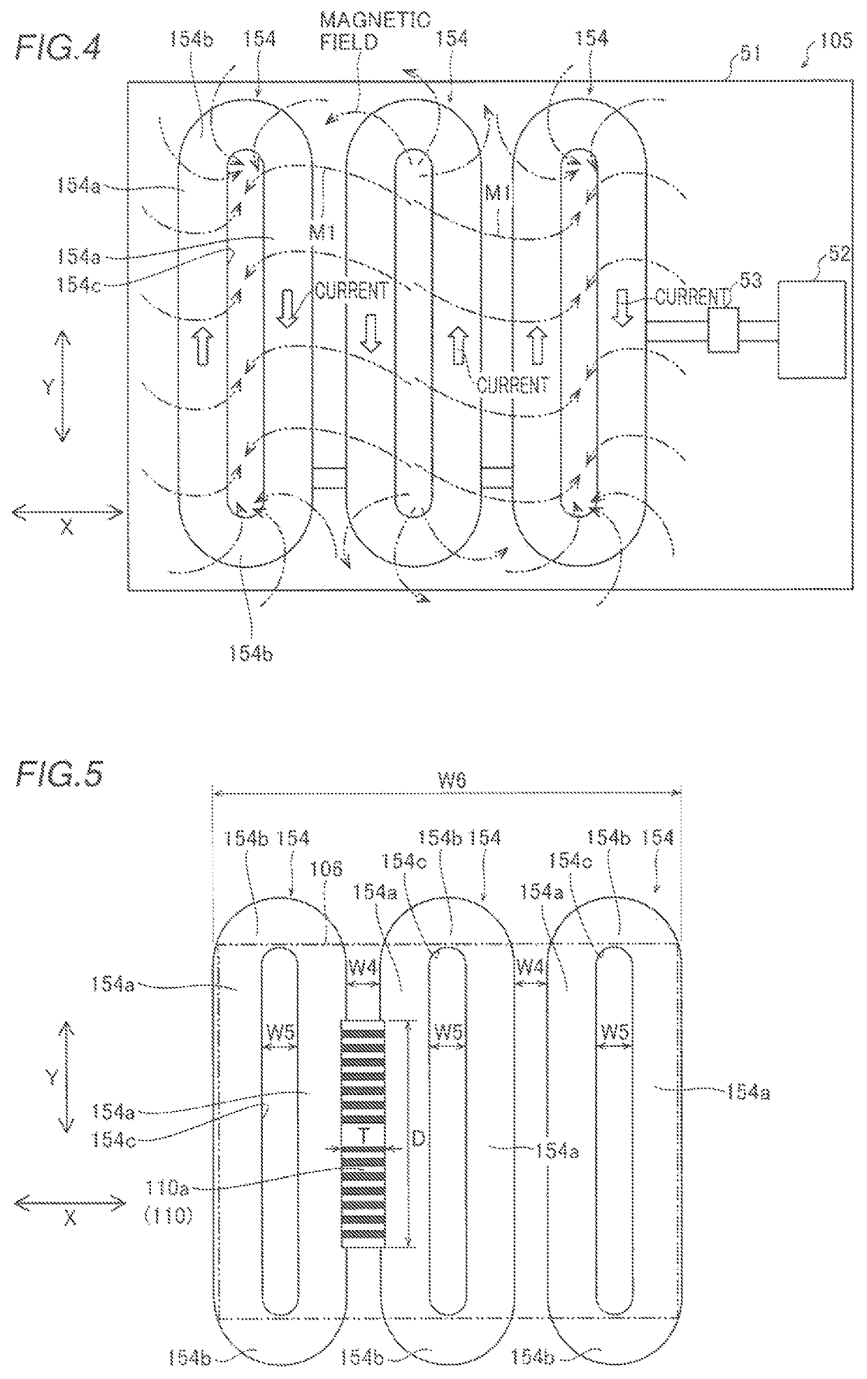
[0043]A second embodiment is now described with reference to FIGS. 1, 4, and 5. In this second embodiment, a plurality of air core coils is provided in one coin detection antenna unlike the first embodiment. The same structures as those of the first embodiment are denoted by the same reference numerals, to omit the description.

Structure of Coin Processing Device

[0044]As shown in FIGS. 1 and 4, a coin processing device 200 according to the second embodiment is different from the coin processing device 100 according to the first embodiment in that the coin processing device 200 includes a coin detection antenna 105.

[0045]According to the second embodiment, the coin detection antenna 105 includes a plurality of (three) air core coils 154. The plurality of air core coils 154 is provided on one substrate 51. The plurality of air core coils 154 is connected in series.

[0046]According to the second embodiment, the plurality of air core coils 154 is disposed along the short-side direction (d...

modified examples

[0057]The embodiments disclosed this time must be considered as illustrative in all points and not restrictive. The scope of the present invention is not shown by the above description of the embodiments but by the scope of claims for patent, and all modifications (modified examples) within the meaning and scope equivalent to the scope of claims for patent are further included.

[0058]For example, while the present invention is applied to the coin processing device as a change machine in each of the aforementioned first and second embodiments, the present invention is not restricted to this. The present invention may alternatively be applied to a coin processing device other than a change machine as long as the coin processing device includes a coin retaining unit and a coin detection antenna.

[0059]While the length of each of the linear portions of the air core coil(s) in the direction in which the linear portions extend is equal to or more than the diameter of the smallest coin in ea...


PUM

PropertyMeasurementUnit
thicknessaaaaaaaaaa
widthaaaaaaaaaa
lengthaaaaaaaaaa

Abstract

A coin detection antenna includes a substrate and an air core coil in a track shape including a wiring pattern provided on the substrate, and a width of an air core of the air core coil in a short-side direction is equal to or less than twice a thickness of a smallest coin having a smallest thickness of coins to be detected.

Description

CROSS-REFERENCE TO RELATED APPLICATION[0001]The present application claims a priority of Japanese Patent Application number JP2017-226576, Coin Detection Antenna and Coin Processing Device, filed Nov. 27, 2017, and is hereby incorporated by reference.BACKGROUND OF THE INVENTIONField of the Invention[0002]The present invention relates to a coin detection antenna and a coin processing device, and more particularly, it relates to a coin detection antenna and a coin processing device each including an air core coil.Description of the Background Art[0003]A coin processing device including an air core coil is known in general, as disclosed in Japanese Patent Laid-Open No. 2017-058861, for example.[0004]Japanese Patent Laid-Open No. 2017-058861 discloses a coin change machine (coin processing device) that performs input and output of coins. The coin change machine includes a coin slot through which coins are inserted, and a tray to which coins are discharged. A sensor element that detects ...

Claims


Application Information

Patent Timeline
Patent Type & Authority Patents(United States)
IPC IPC(8): G07D5/02H01Q9/27G07D3/14G07D5/10H01F21/00H01F5/00G07D5/08G07D9/02
CPCH01F5/003G07D3/14G07D5/08H01Q9/27G07D5/10H01F21/005G07D5/02G07D9/02
Inventor NAGASHIMA, RYUUICHI
Owner FUJI ELECTRIC CO LTD
Why Eureka
Try Eureka