
Battery pack and encapsulated interconnection for a battery pack

a battery pack and encapsulation technology, applied in the direction of batteries, sustainable manufacturing/processing, cell components, etc., can solve the problems of reducing the life of rechargeable batteries, deteriorating charging and discharging performance of rechargeable batteries, and unable to generate the desired amount of power of batteries, so as to relieve the stress on the coolant interconnector and dissipate flow energy

Active Publication Date: 2020-03-10
SAMSUNG SDI CO LTD
View PDF15 Cites 0 Cited by
  • Summary
  • Abstract
  • Description
  • Claims
  • Application Information

AI Technical Summary

Benefits of technology

The design improves mechanical stability and reduces the risk of coolant leakage, ensuring efficient heat dissipation and protection against coolant damage, thereby enhancing the performance and safety of battery packs in electric vehicles.

Problems solved by technology

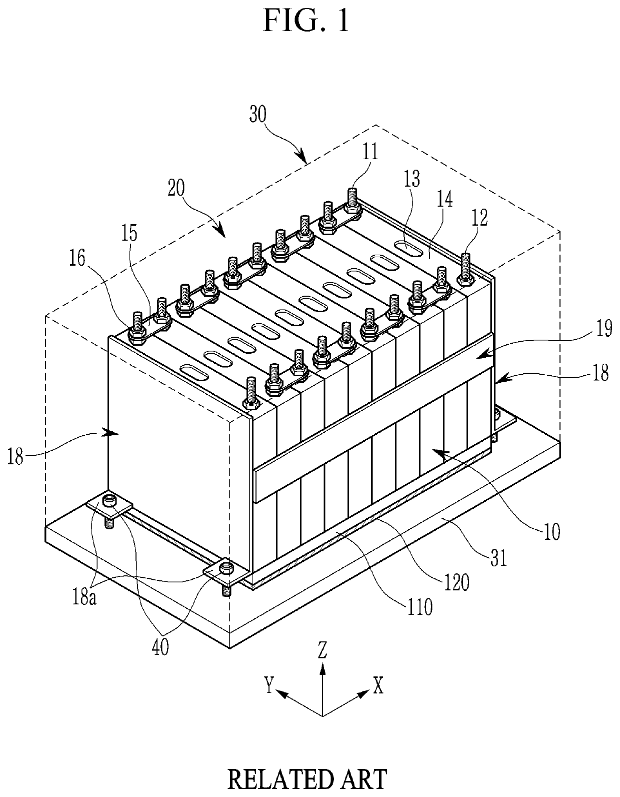
If there is insufficient heat emission / discharge / dissipation, a temperature deviation occurs between the battery cells such that the battery module cannot generate the desired amount of power.
In addition, when the internal temperature of the battery cells increases (e.g., increases due to the heat generated thereby), abnormal reactions occur in the battery cells such that charging and discharging performance of the rechargeable batteries deteriorates and the life-span of the rechargeable batteries is reduced.
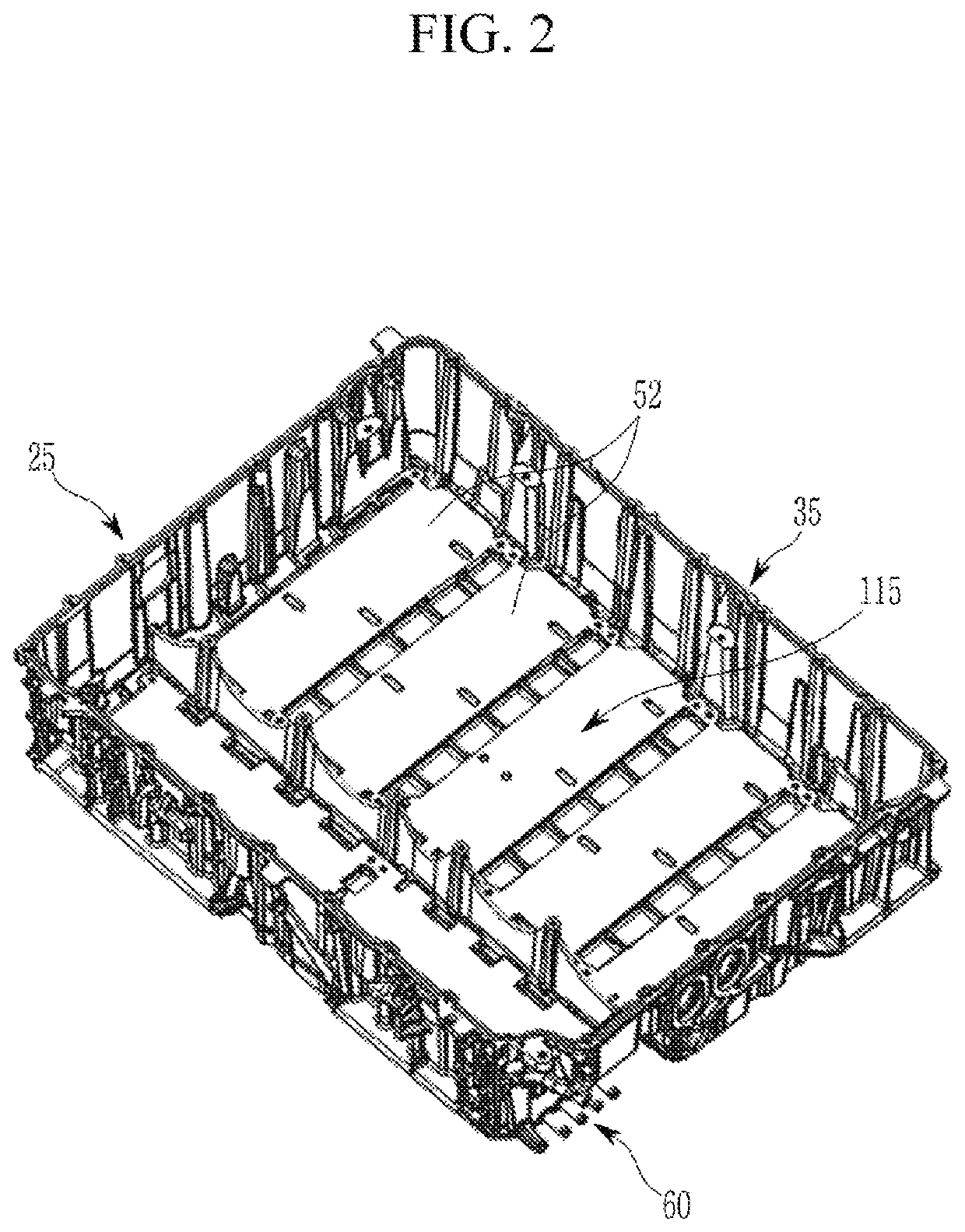
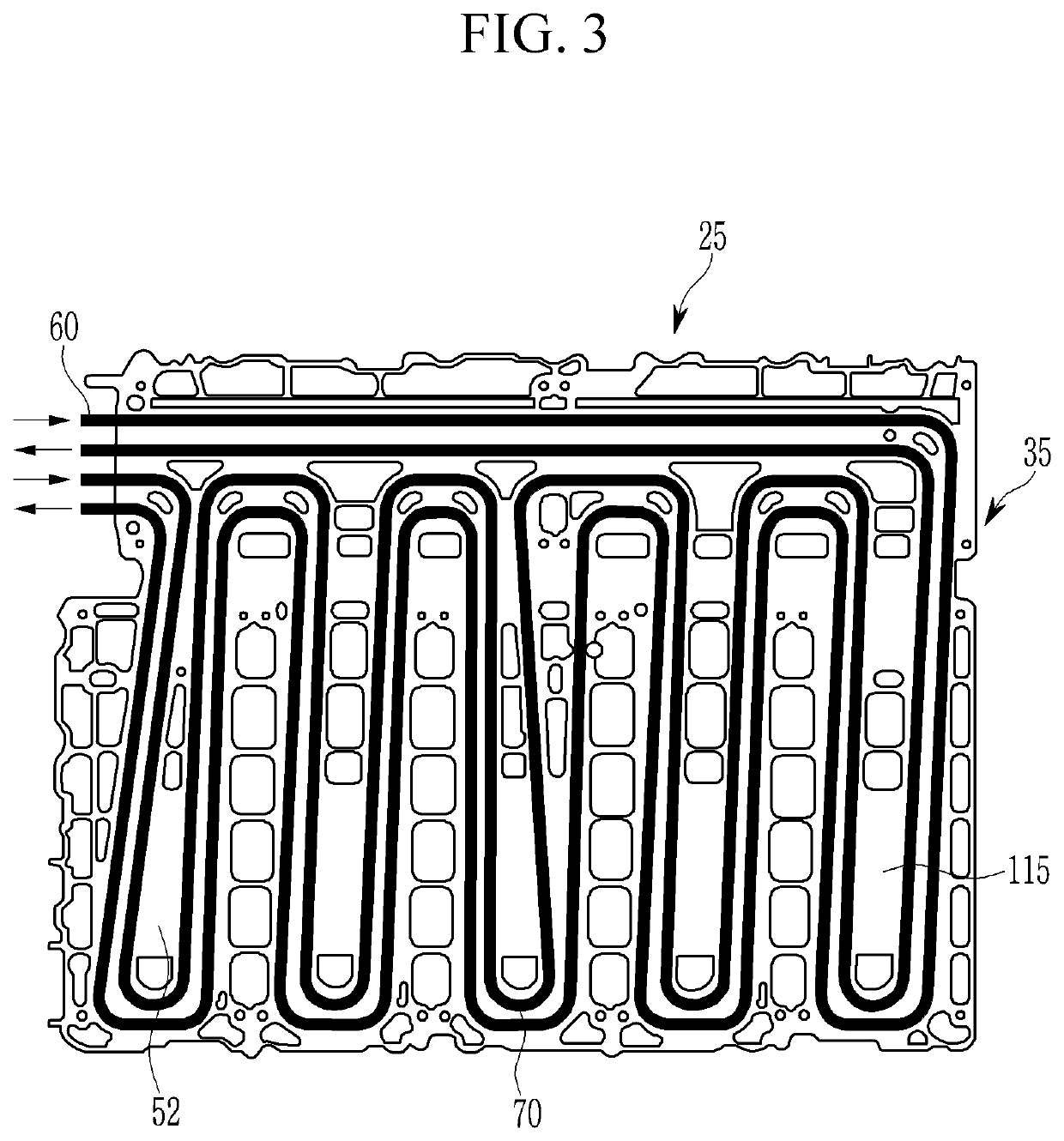
The structures for distributing coolant to a plurality of battery modules are generally weak points of the battery pack in terms of mechanical stability and rigidity, both during normal use and in a crash situation.
In addition, depending on the type of secondary battery included in the battery modules, for example, a lithium ion battery, and the type of used coolant, for example, water-based coolants, leaking coolant may severely damage the battery modules and even surrounding structures, for example, surrounding structures in an electric vehicle.

Method used


Image

  • Battery pack and encapsulated interconnection for a battery pack
  • Battery pack and encapsulated interconnection for a battery pack
  • Battery pack and encapsulated interconnection for a battery pack

Examples


Embodiment Construction

[0045]It will be understood that when an element or layer is referred to as being “on,”“connected to,” or “coupled to” another element or layer, it may be directly on, connected, or coupled to the other element or layer or one or more intervening elements or layers may also be present. When an element or layer is referred to as being “directly on,”“directly connected to,” or “directly coupled to” another element or layer, there are no intervening elements or layers present. For example, when a first element is described as being “coupled” or “connected” to a second element, the first element may be directly coupled or connected to the second element or the first element may be indirectly coupled or connected to the second element via one or more intervening elements. The same reference numerals designate the same elements. As used herein, the term “and / or” includes any and all combinations of one or more of the associated listed items. Further, the use of “may” when describing embod...


PUM

PropertyMeasurementUnit
areaaaaaaaaaaa
volumeaaaaaaaaaa
areasaaaaaaaaaa

Abstract

A battery pack includes a first battery module level and a second battery module level. The first battery module level includes: a first heat exchanger including a cooling tube that defines a cooling area; a first secondary battery cell in thermal contact with the first heat exchanger at the cooling area; a coolant distributor line outside the first heat exchanger and configured to supply coolant to the cooling tube; a coolant interconnector fluidly connecting the cooling tube or the coolant distributor line to the second battery module level; and an encapsulation element enclosing the coolant interconnector and confining a volume in which the coolant interconnector is arranged between the first battery module level and the second battery module level.

Description

CROSS-REFERENCE TO RELATED APPLICATION[0001]This application claims priority to and the benefit of European Patent Application No. 16186797.3, filed on Sep. 1, 2016 in the European Patent Office, which is incorporated herein in its entirely by reference.BACKGROUND[0002]1. Field[0003]Aspects of embodiments of the present invention relate to a battery pack and an encapsulated interconnection for a battery pack.[0004]2. Description of the Related Art[0005]A rechargeable battery (e.g., a secondary battery) differs from a primary battery in that it is designed to be repeatedly charged and discharged, while the latter provides an irreversible conversion of chemical to electrical energy. Low-capacity rechargeable batteries are used as power supplies for, as an example, small electronic devices, such as cellular phones, notebook computers, and camcorders, while high-capacity rechargeable batteries are used as power supplies for, as an example, motors in hybrid vehicles and the like.[0006]In...

Claims


Application Information

Patent Timeline
Patent Type & Authority Patents(United States)
IPC IPC(8): H01M10/6557H01M10/613H01M10/625H01M2/10H01M10/6556H01M10/6567F28D21/00H01M50/204
CPCH01M10/6557H01M2/1077H01M10/625H01M10/613H01M10/6567H01M10/6556H01M2220/20F28D2021/0043H01M10/058H01M50/204Y02E60/10Y02P70/50H01M10/655H01M50/183H01M50/24H01M50/20
Inventor WUENSCHE, RALPHSTOJANOVIC, OLIVERKRIEGER, HORST
Owner SAMSUNG SDI CO LTD
Learn More