
Intercooler

a technology of intercooler and cooling water, which is applied in the direction of combustion engines, lighting and heating apparatus, machines/engines, etc., can solve the problems of large pressure loss of cooling water generated when the cooling water flows through the high-temperature heat exchange part, and the cooling water may boil, so as to suppress the burning of the heat medium

Active Publication Date: 2020-01-28
DENSO CORP
View PDF19 Cites 0 Cited by
  • Summary
  • Abstract
  • Description
  • Claims
  • Application Information

AI Technical Summary

Benefits of technology

The patent text is discussing a way to prevent boiling of the cooling water in an intercooler that cools supercharged intake air. The text describes a method that uses two heat mediums with different temperatures to cool the air. The first heat medium cools the air before it reaches the intercooler, and the second heat medium cools the air after it passes through the intercooler. The second heat medium has a lower temperature than the first, which prevents boiling of the cooling water in the intercooler. This method helps to maintain the strength of the parts in the intercooler and ensures continued cooling performance.

Problems solved by technology

Therefore, since the width of each of the cooling water flow passages is narrow, the pressure loss of the cooling water generated when the cooling water flows through the high-temperature heat exchange part is large.
As a result, the cooling water may boil on the outlet side of the upstream cooling water passage in the high-temperature heat exchange part.

Method used


Image

  • Intercooler
  • Intercooler
  • Intercooler

Examples


first embodiment

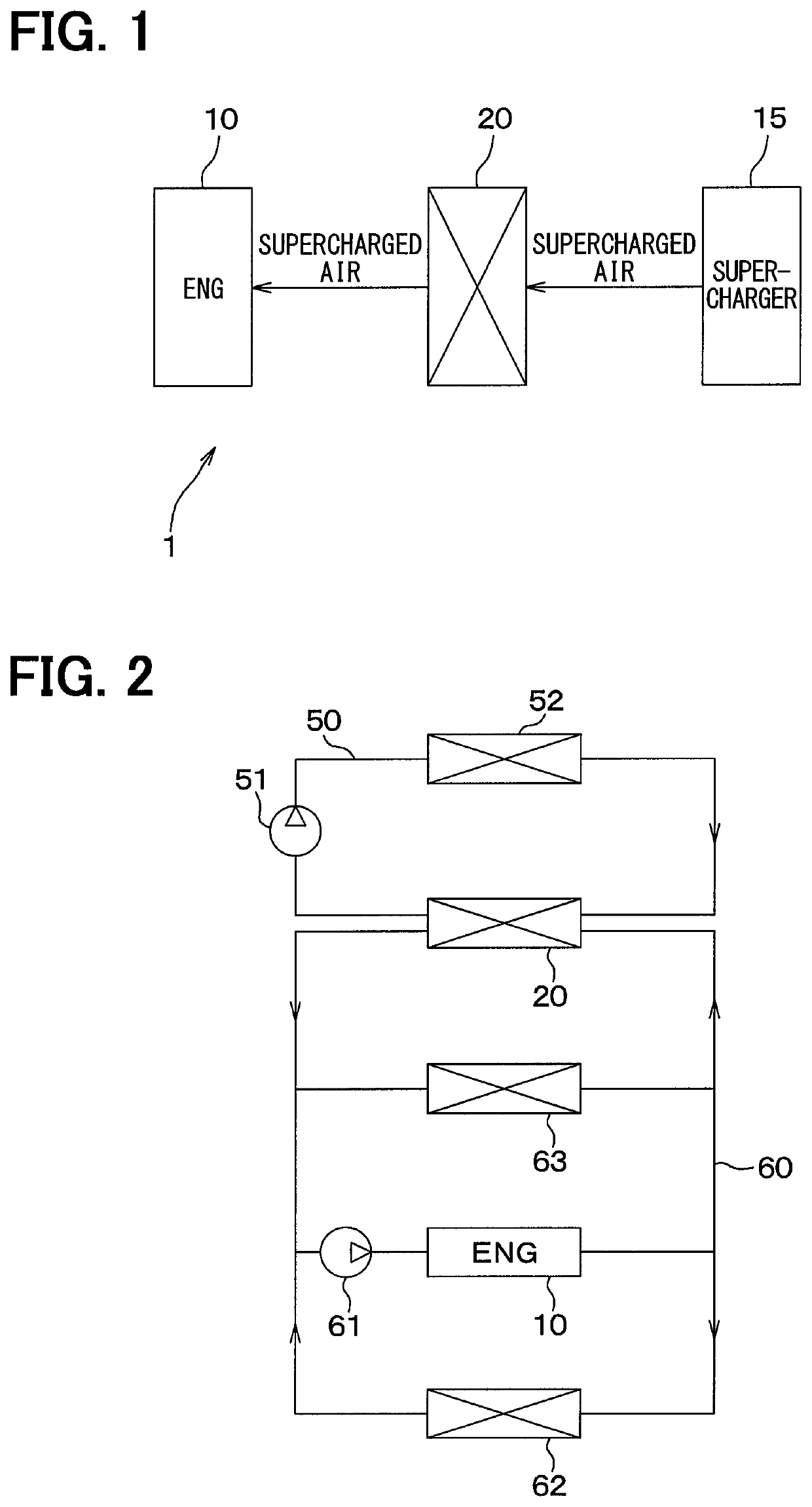
[0035]A first embodiment of the present disclosure will be described with reference to the drawings. In the present embodiment, an example in which an intercooler 20 of the present disclosure is applied to a supercharged intake air cooling system 1 for a vehicle will be described.

[0036]A supercharger 15 for supercharging intake air to an engine 10 is provided in an intake air system of the engine 10 of the vehicle (that is, an internal combustion engine), as shown in FIG. 1. This supercharger 15 is provided to compensate for the maximum output of the engine 10. That is, the vehicle of the present embodiment has the engine 10 made smaller for higher fuel efficiency and the supercharger 15 is used to compensate for the maximum output reduced in exchange for making the engine 10 smaller.

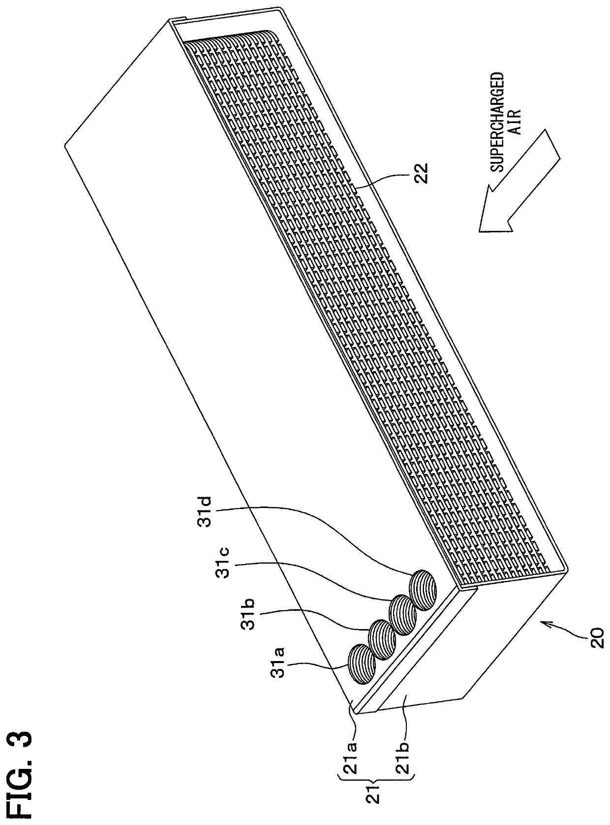
[0037]An intercooler 20 cooling intake air of the engine 10 is located downstream of the supercharger 15 in the intake air system with respect to a flow of the intake air. The intercooler 20 cools the s...

first modification

of First Embodiment

[0117]In the first embodiment, the rib 41 is formed by combining the protrusion portion 41a of the plate 25a and the protrusion portion 41b of the plate 25b. However, instead of this, the rib 41 may be formed as shown in FIG. 12.

[0118]That is, in the first modification, no protrusion portion is provided on the plate 25b, and an upper portion 25c of the plate 25b facing the plate 25a is formed in a planar shape.

[0119]The protrusion portion of the plate 25a joined to the upper portion 25c of the plate 25b is the rib 41 that is the boiling suppression member. The protrusion portion of the plate 25a is convex to the plate 25b from the plate 25a side.

second modification

of First Embodiment

[0120]In the first embodiment, the rib 41 is formed by combining the protrusion portion 41a of the plate 25a and the protrusion portion 41b of the plate 25b. However, instead of this, the rib 41 may be formed as shown in FIG. 13.

[0121]That is, in the second modification, no protrusion portion is provided on the plate 25a, and a lower portion 25d of the plate 25a facing the plate 25b is formed in a planar shape.

[0122]The protrusion portion of the plate 25b joined to the lower portion 25d of the plate 25a is the rib 41 that is the boiling suppression member. The protrusion portion of the plate 25b is convex to the plate 25a from the plate 25b side.


PUM


Abstract

An intercooler includes a heat exchanger that has a first heat exchange portion through which a first heat exchange medium flows and a second heat exchange portion through which a second heat exchange medium flows. The first heat exchange medium flowing through the first heat exchange portion cools the supercharged intake air by exchanging heat with the supercharged intake air. The second heat exchange medium flowing through the second heat exchange portion cools the supercharged intake air by exchanging heat with the supercharged intake air. The heat exchanger includes an inner fin configured to enhance the heat exchange between the supercharged intake air and the first heat exchange medium. The heat exchanger includes a boiling suppression portion configured to suppress a boiling of the first heat exchange medium flowing in an upstream part, in a flow direction of the supercharged intake air, of the first heat exchange portion.

Description

CROSS REFERENCE TO RELATED APPLICATIONS[0001]This application is a U.S. National Phase Application under 35 U.S.C. 371 of International Application No. PCT / JP2017 / 009769 filed on Mar. 10, 2017. This application is based on and claims the benefit of priority from Japanese Patent Application No. 2016-070719 filed on Mar. 31, 2016. The entire disclosures of all of the above applications are incorporated herein by reference.TECHNICAL FIELD[0002]The present disclosure relates to an intercooler for cooling intake air supercharged by a supercharger.BACKGROUND ART[0003]Conventionally, an intercooler includes a high-temperature heat exchange portion in which supercharged air supercharged to an engine by a supercharger is cooled by using first cooling water, and a low-temperature heat exchange portion in which the supercharged air is cooled by using second cooling water whose temperature is lower than that of the first cooling water. For example, such intercooler is described in Patent Docume...

Claims


Application Information

Patent Timeline
Patent Type & Authority Patents(United States)
IPC IPC(8): F02B29/04F28D9/00
CPCF28D9/0043F02B29/04F02B29/0443F02B29/0462Y02T10/146Y02T10/12
Inventor KAWAGUCHI, TAKEFUMIKUROYANAGI, ISAOHARADA, MASAKI
Owner DENSO CORP
Learn More