
Magnetic field falling particle solar receiver systems and methods

Active Publication Date: 2019-12-10
NAT TECH & ENG SOLUTIONS OF SANDIA LLC
View PDF6 Cites 2 Cited by
  • Summary
  • Abstract
  • Description
  • Claims
  • Application Information

AI Technical Summary

Benefits of technology

The present invention provides systems and methods for improving heat transfer and mixing within particles falling through a solar receiver. The falling particle receiver imposes a magnetic field to increase the residence time of particles falling through the receiver, resulting in more uniform heating of the particles. The magnetic field also reduces particle flow destabilization and increases the travel distance of particles through the receiver, resulting in more uniform particle outlet temperatures. The "heat-filtering" effect of the magnetic field also allows for increased residence times for larger particles, which may heat slower, leading to improved overall efficiency of the solar receiver.

Problems solved by technology

Solar energy offers a clean, inexhaustible, sustainable solution to energy demands and has the potential to supply a very significant fraction of U.S. and global electricity consumption.
While the U.S. and global solar power potential is known to be immense, solar power systems have not been economically competitive without government support, to date.
Direct absorption solid particle receivers that employ this methodology have the potential to achieve heat-transfer media temperatures of ˜1000° C. However, depending on particle size and external forces that can alter particle flow (e.g., external wind and flow due to convective heat losses); optimized particle flow can be severely affected, which can reduce the receiver efficiency.
These previously disclosed processes and systems are not efficient in capturing solar energy to heat particles, which increase costs.

Method used


Image

  • Magnetic field falling particle solar receiver systems and methods
  • Magnetic field falling particle solar receiver systems and methods
  • Magnetic field falling particle solar receiver systems and methods

Examples


Embodiment Construction

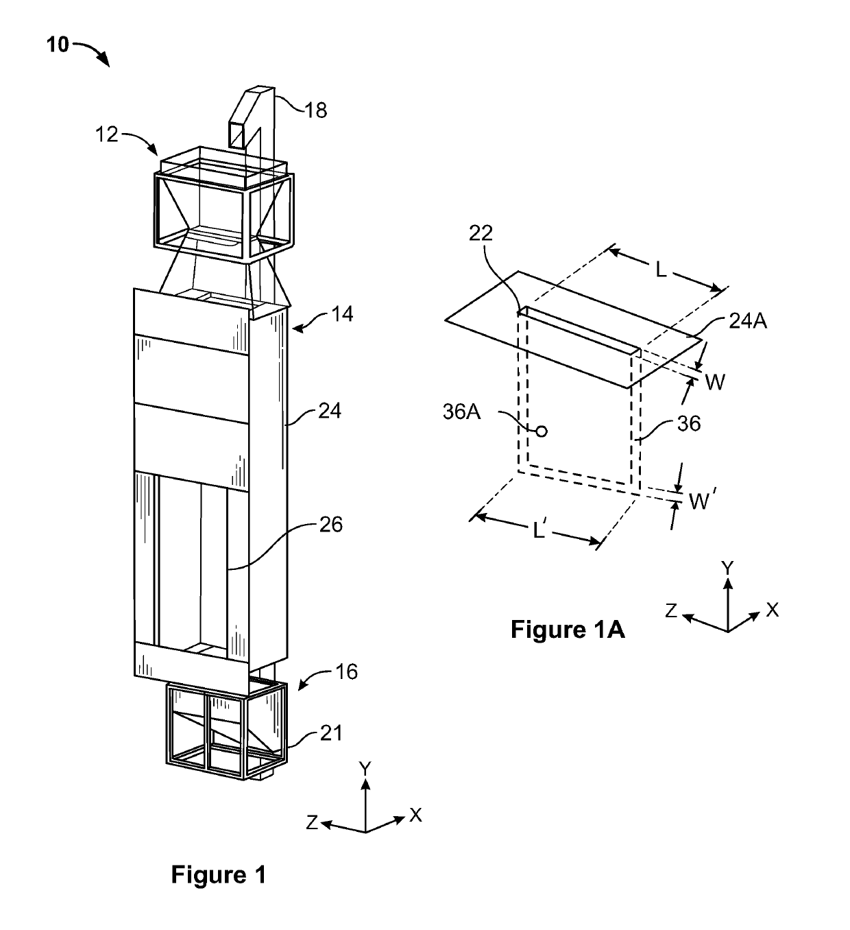
[0024]The present invention now will be described more fully hereinafter with reference to the accompanying drawings, in which preferred embodiments of the invention are shown. This invention may, however, be embodied in many different forms and should not be construed as limited to the embodiments set forth herein; rather, these embodiments are provided so that this disclosure will be thorough and complete and will fully convey the scope of the invention to those skilled in the art.

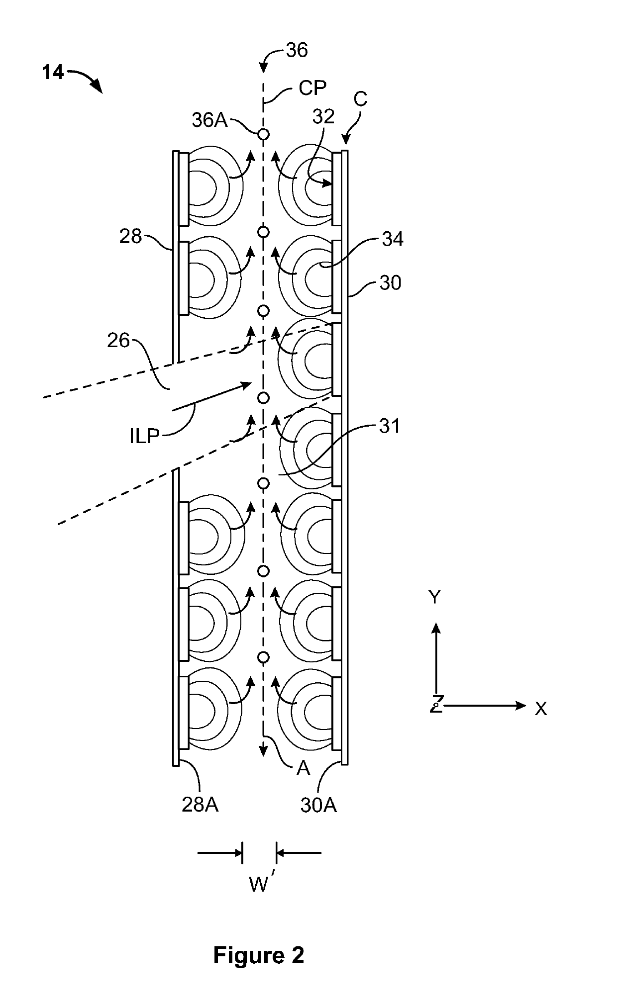
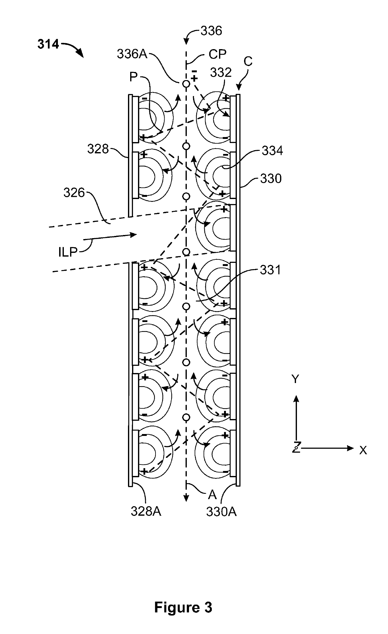
[0025]The magnetic field may be imposed upon particles selected from the group including (1) diamagnetic particles, (2) paramagnetic / ferromagnetic particles and (3) non-magnetic charged particles. The approaches vary based on directionality, strength and mechanism of particle magnetic moments μ. In an embodiment, the disclosed CSP receivers may operate at temperatures above 700° C., and may include storage capabilities which can be used to reduce levelized cost of electricity (LCOE).

[0026]According to an...


PUM


Abstract

Systems and methods that increase the residence time of particles falling through a solar receiver using an induced magnetic field to suspend or slow down and / or alter the flight path of the particles falling through the concentrated beam of sunlight are disclosed.

Description

CROSS-REFERENCE TO RELATED APPLICATIONS[0001]This application claims benefit of U.S. Provisional Patent Application No. 61 / 154,922, “MAGNETIC FIELD FALLING PARTICLE SOLAR RECEIVER SYSTEMS AND METHODS”, filed Apr. 30, 2015, which is incorporated by reference herein in its entirety.STATEMENT OF GOVERNMENT INTEREST[0002]The United States Government has rights in this invention pursuant to Contract No. DE-AC04-94AL85000 between the United States Department of Energy and Sandia Corporation, for the operation of the Sandia National Laboratories.FIELD[0003]The present disclosure is generally directed to solar energy. The present disclosure is more particularly directed to controlling falling particle flow through solar receivers by magnetic fields.BACKGROUND[0004]Solar power systems offer much promise for clean energy, with few, or zero, carbon emissions. These systems collect incident sunlight and convert this sunlight into a usable form of power, such as heat or electricity. Solar energy...

Claims


Application Information

Patent Timeline
IPC IPC(8): F24S90/00
CPCF24S90/00Y02E10/40
Inventor ARMIJO, KENNETH M.ANDERSON, RYAN R.BABINIEC, SEAN MICHAELHO, CLIFFORD K.MAZUMDER, MALAY
Owner NAT TECH & ENG SOLUTIONS OF SANDIA LLC
Learn More