
Cuboid inertial measurement unit

a technology of inertial measurement and cuboid, which is applied in the direction of speed measurement using gyroscopic effects, instruments, navigation instruments, etc., can solve the problems of low cost, compact and consuming little power, and limitations of mems technology, and achieve cost-effective, low-power, lightweight solutions, and quick and accurate rotation measurements.

Active Publication Date: 2019-11-12
CUBIC CORPORATION
View PDF20 Cites 0 Cited by
  • Summary
  • Abstract
  • Description
  • Claims
  • Application Information

AI Technical Summary

Benefits of technology

The present invention is about inertial measurement units (IMUs) that are designed to accurately measure rotation of a body quickly and in non-linear or non-stationary applications. The IMUs use MEMS gyroscopes arranged on a substrate which provide cost-effective, low-power, and lightweight solutions. The arrangement of the MEMS gyroscopes is designed to provide easy interpretation of rotation results even in the presence of noise. The IMUs also use novel filtering and correction techniques to quickly determine the reliability of sensor data and account for it, which allows the generation of accurate results even with a short number of sensor data cycles. This eliminates the need for long-term averaging of sensor data.

Problems solved by technology

These are typically microelectromechanical systems (MEMS) based, low cost, very compact and consume little power.
However, limitations of MEMS technology, especially the typical devices found in mobile devices, include stability and noise issues.
Bearing is typically determined using magnetometers in combination with Global Navigation Satellite Systems (GNSS) receivers, so magnetic distortions can cause false readings while the loss of signal from GNSS when travelling in tunnels or buildings can results in a loss of position and orientation.
However, MEMS gyroscopes are very noisy and suffer from environmentally induced errors.
The issue with the latter approach is that it only really works when the filter is stationary and does not function well in a dynamic environment.
However, this technique will not facilitate the measurement of the Earth's rotation with currently available MEMS sensors.

Method used


Image

  • Cuboid inertial measurement unit
  • Cuboid inertial measurement unit
  • Cuboid inertial measurement unit

Examples


Embodiment Construction

[0022]The subject matter of embodiments of the present invention is described here with specificity to meet statutory requirements, but this description is not necessarily intended to limit the scope of the claims. The claimed subject matter may be embodied in other ways, may include different elements or steps, and may be used in conjunction with other existing or future technologies. This description should not be interpreted as implying any particular order or arrangement among or between various steps or elements except when the order of individual steps or arrangement of elements is explicitly described.

[0023]Embodiments of the present invention are generally related to low-cost compact devices capable of providing navigation bearing information in the presences of magnetic anomalies such as iron or magnets. Applications may exist for mobile devices (cell phones, personal media players, etc.). It will be appreciated that a person of skill in the art will understand that alterna...


PUM


Abstract

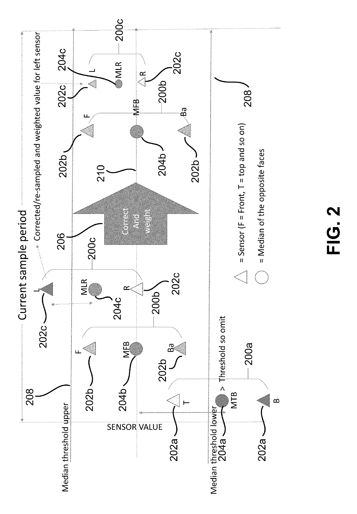
An inertial measurement unit includes a substrate having MEMS gyroscopes arranged on the substrate as opposing pairs. The gyroscopes of each opposing pair are arranged on opposite sides of an axis of rotation of the substrate and each opposing pair has a central axis that intersects an axis of rotation of the substrate. A processor receives a rotational measurement from each gyroscope, compares the measurements from gyroscopes of each opposing pair, determines a mean or median rotation value for each opposing pair, and compares the mean or median rotation value with a threshold value. The processor assigns a weight to the mean or median value for each opposing pair and determines a rotation of the cuboid inertial measurement unit based on the mean or median value for each opposing pair and the respective weight for the mean or median value for each opposing pair.

Description

CROSS-REFERENCES TO RELATED APPLICATIONS[0001]This Application claims priority to U.S. Provisional Patent Application No. 62 / 618,507, filed Jan. 17, 2018, entitled “CUBOID INERTIAL MEASUREMENT UNIT,” the entire disclosure of which is hereby incorporated by reference, for all purposes, as if fully set forth herein.BACKGROUND OF THE INVENTION[0002]In applications where large, heavy, and / or expensive inertial measurement units (IMUs) are not practical, such as in mobile telephones, portable navigation devices, other handheld devices, and the like, magnetometers combined with gyroscopes and accelerometers are often used. These are typically microelectromechanical systems (MEMS) based, low cost, very compact and consume little power. However, limitations of MEMS technology, especially the typical devices found in mobile devices, include stability and noise issues. Bearing is typically determined using magnetometers in combination with Global Navigation Satellite Systems (GNSS) receivers,...

Claims


Application Information

Patent Timeline
Patent Type & Authority Patents(United States)
IPC IPC(8): G01C19/5776G01C21/16G01C19/5783
CPCG01C21/16G01C19/5776G01C19/5783G01C21/166
Inventor FOX, ANDREW JOHNPARRY, MATTHEWBRADLEY, BYRON
Owner CUBIC CORPORATION
Learn More