
Optical laminate, polarizing plate and organic EL display device

a technology of optical laminate and polarizing plate, applied in the direction of polarising elements, identification means, instruments, etc., can solve the problems of reducing contrast and reflecting glare, and achieve the effect of suppressing uneven film thickness

Active Publication Date: 2019-10-29
FUJIFILM CORP
View PDF27 Cites 1 Cited by
  • Summary
  • Abstract
  • Description
  • Claims
  • Application Information

AI Technical Summary

Benefits of technology

This configuration effectively suppresses cissing and film thickness unevenness, enhancing the performance and contrast of the organic EL display devices by maintaining uniformity and preventing reflection issues.

Problems solved by technology

For example, since an organic EL display device has a structure in which layers having different refractive indexes are laminated or a structure in which metal electrodes are used, there arises a problem that external light is reflected in the interfaces of each of these layers to cause a reduction in contrast and reflected glare, or the like.

Method used


Image

  • Optical laminate, polarizing plate and organic EL display device
  • Optical laminate, polarizing plate and organic EL display device
  • Optical laminate, polarizing plate and organic EL display device

Examples


example 1

[0200]An optical laminate was prepared in the same manner as in Comparative Example 1 except that in the composition of the optically anisotropic layer coating liquid (B), 5 parts by mass of ethylene oxide-modified trimethylolpropane triacrylate (V#360, manufactured by OSAKA ORGANIC CHEMICAL INDUSTRY LTD.) was formulated as a non-liquid crystal monomer.

example 2

[0203]An optical laminate was prepared in the same manner as in Comparative Example 1 except that in the composition of the optically anisotropic layer coating liquid (B), the ratio of the repeating unit a (F part) of the fluorine-based polymer (FP2), as an alignment controlling agent, was changed to the value shown in Table 1 below.

examples 3 and 4

[0204]Optical laminates were prepared in the same manner as in Comparative Example 1 except that in the composition of the optically anisotropic layer coating liquid (B), the ratio of the repeating unit a (F part) of the fluorine-based polymer (FP2), as an alignment controlling agent, was changed to values shown in Table 1 below so that the amount added with respect to the total solid content was changed to the values shown in table 1 below.


PUM

PropertyMeasurementUnit
surface energyaaaaaaaaaa

Abstract

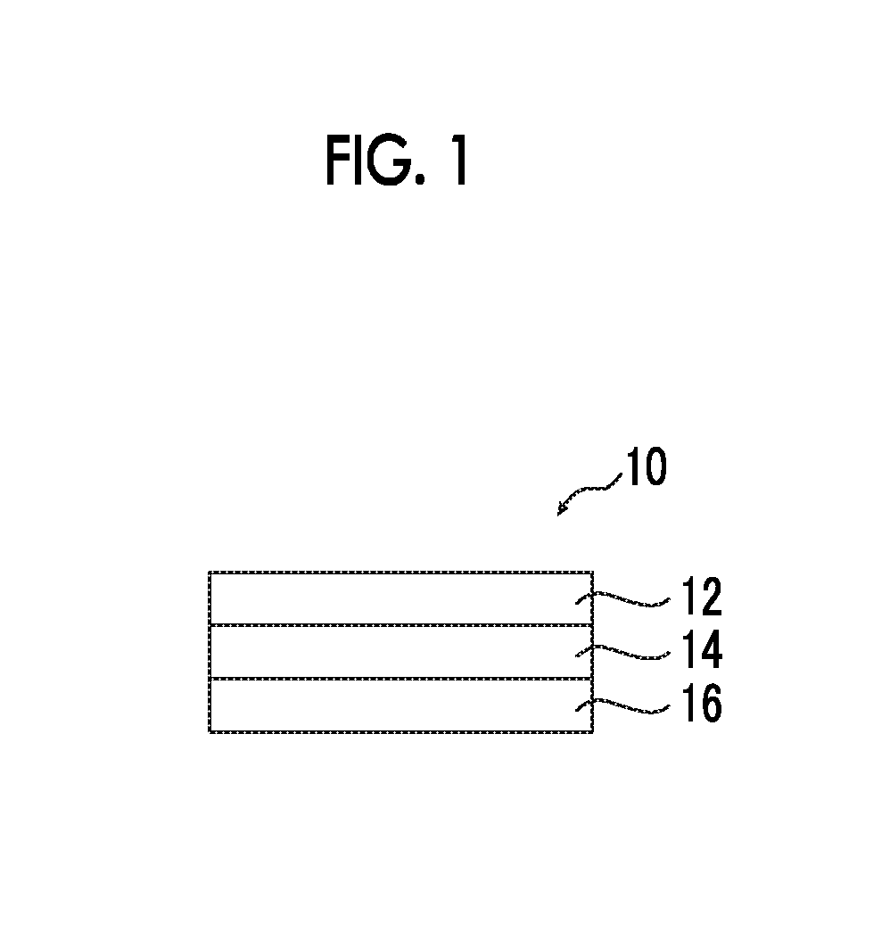
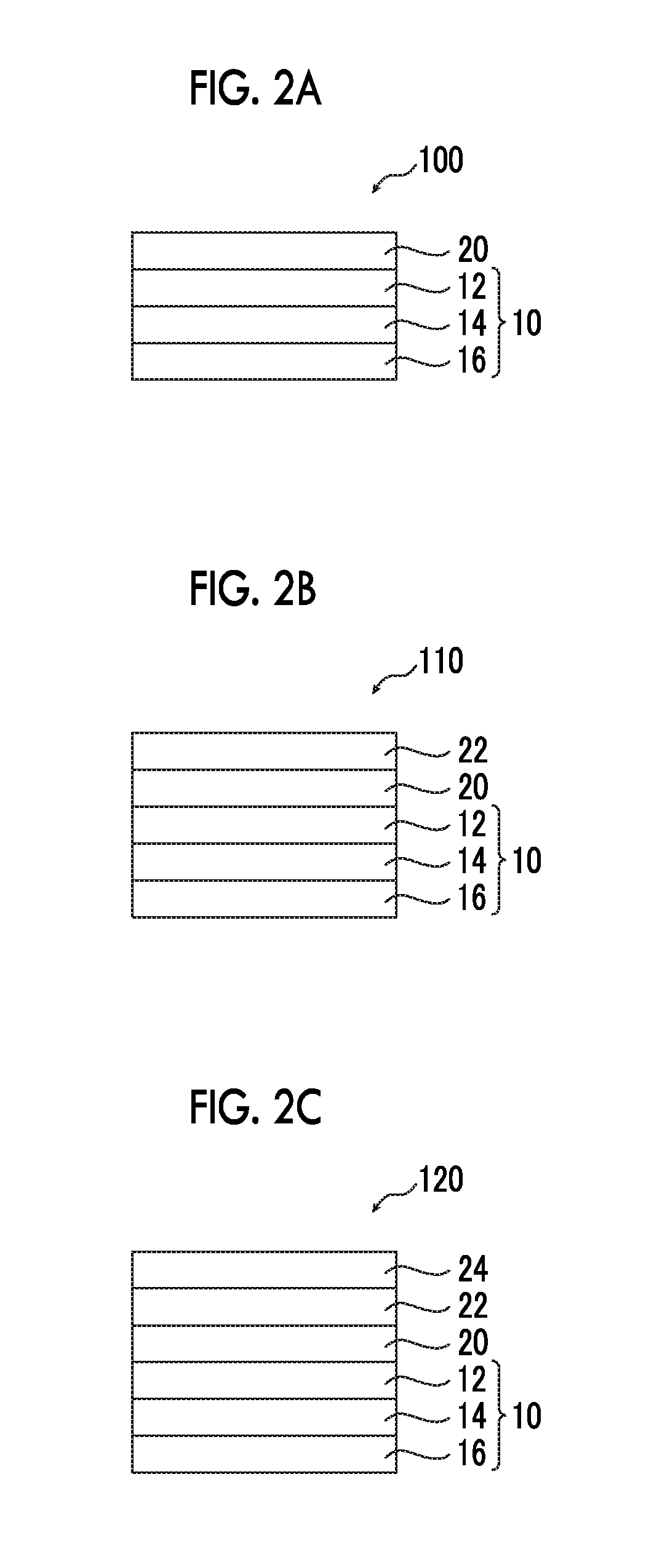
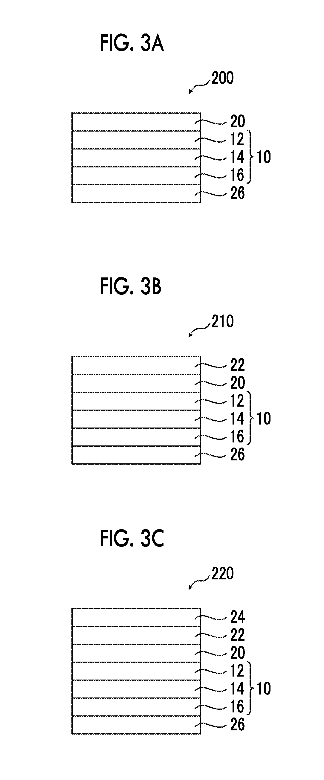
The present invention provides an optical laminate in which cissing occurring when an optically anisotropic layer is formed and film thickness unevenness are suppressed, and a polarizing plate and an organic EL display device using the same. The optical laminate includes an optically anisotropic layer A, and an optically anisotropic layer B, where layer A and layer B come into direct contact, either or both of layer A and layer B are formed of a composition containing a liquid crystal compound, surface energy A of a surface of layer A on a side in contact with layer B is 30 to 40 mN / m, surface energy B1 of a surface of layer B on a side in contact with layer A is 35 mN / m or more, and surface energy B2 of a surface of layer B opposite to the side in contact with layer A is 25 mN / m or less.

Description

CROSS-REFERENCE TO RELATED APPLICATIONS[0001]This application is a Continuation of PCT International Application No. PCT / JP2015 / 073997 filed on Aug. 26, 2015, which claims priority under 35 U.S.C. § 119(a) to Japanese Patent Application No. 2014-175935 filed on Aug. 29, 2014. The above application is hereby expressly incorporated by reference, in its entirety, into the present application.BACKGROUND OF THE INVENTION[0002]1. Field of the Invention[0003]The present invention relates to an optical laminate, a polarizing plate, and an organic EL display device.[0004]2. Description of the Related Art[0005]A phase difference plate has very numerous applications and is already used for a reflective type liquid crystal display (LCD), a semi-transmissive type LCD, a brightness enhancement film, an organic electroluminescence (EL) display device, a touch panel, and the like. For example, since an organic EL display device has a structure in which layers having different refractive indexes are...

Claims


Application Information

Patent Timeline
Patent Type & Authority Patents(United States)
IPC IPC(8): G02B5/30C09K19/38C09K19/56H01L51/52C09K19/20C09K19/04B32B7/023G02F1/13363G02F1/1335
CPCG02B5/3083H01L51/5281G02B5/3016C09K19/3823C09K19/56C09K19/3809C09K19/3852B32B7/023C09K2019/2078G02F1/13363C09K2019/0448B32B2457/202Y10T428/1041G02F1/133528C09K2219/03G02F2001/133638B32B2457/206B32B2457/20C09K2019/2035C09K2323/031H10K59/8791B32B7/02G02B5/30G09F9/30H05B33/02G02F1/133638H10K50/86
Inventor MARUYAMA, AKIRA
Owner FUJIFILM CORP
Learn More