
Motor control unit and electric power steering apparatus equipped with the same

a technology of motor control unit and electric power steering apparatus, which is applied in the direction of electric generator control, dynamo-electric converter control, dynamo-electric gear control, etc., can solve the problems of insufficient response, noise immunity decrease, and difficulty in making these two compatible, so as to achieve smooth handling and flexible compatibility of responsibility and noise immunity

Active Publication Date: 2019-10-29
NSK LTD
View PDF19 Cites 6 Cited by
  • Summary
  • Abstract
  • Description
  • Claims
  • Application Information

AI Technical Summary

Benefits of technology

The motor control unit described in this patent offers flexibility in how it responds to different situations by changing the way it provides feedback. This allows for smoother and more efficient control over the motor. Additionally, the patent explains how the electric power steering system can be designed to have a desirable response frequency and stationary gain to improve handling performance. Overall, this innovation results in a more effective and efficient motor control system for electric vehicles.

Problems solved by technology

However, it is generally difficult to make these two compatible because the noise immunity decreases when the responsibility of the current control system is made high.
However, a demand for performance of the controller has been upgraded year after year, and even if such a method as in Patent Document 1 makes the responsibility and the noise immunity compatible to a high degree, there is the case where a response is insufficient since a demanded performance is changed in accordance with a state of an electric power steering apparatus (EPS).

Method used


Image

  • Motor control unit and electric power steering apparatus equipped with the same
  • Motor control unit and electric power steering apparatus equipped with the same
  • Motor control unit and electric power steering apparatus equipped with the same

Examples


first embodiment

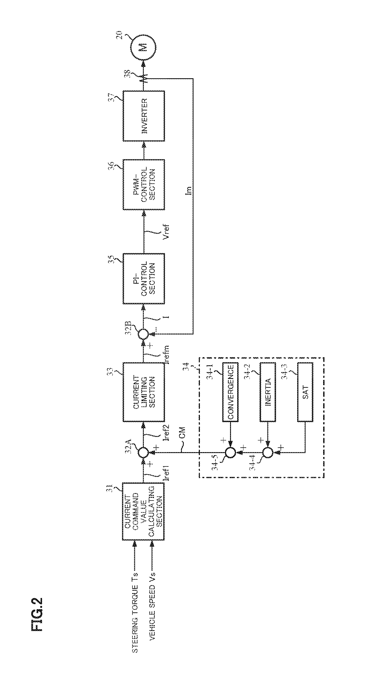
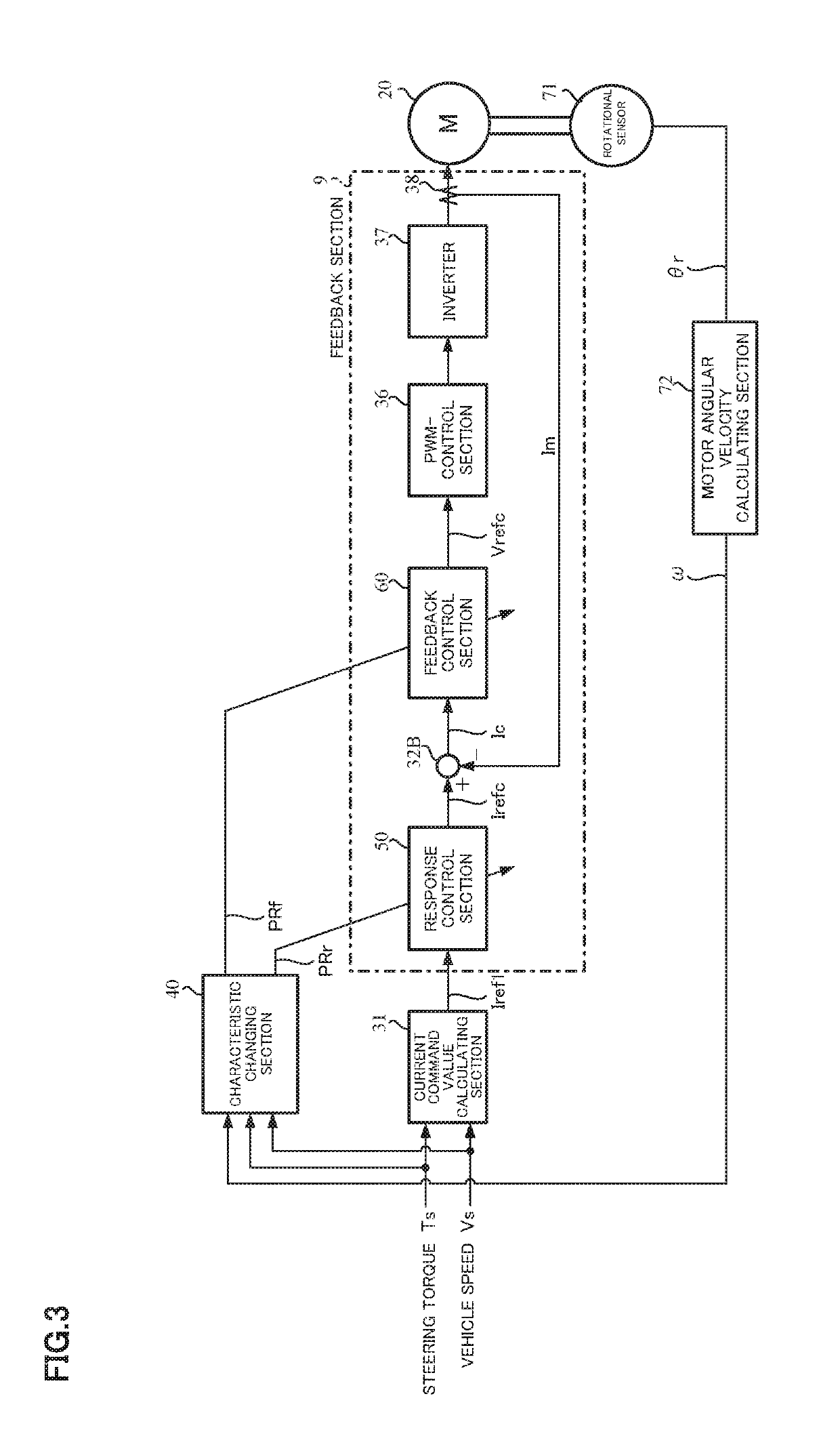
[0048]FIG. 3 shows a configuration example (a first embodiment) of an embodiment of the present invention corresponding to FIG. 2, the same configurations are designated with the same numerals, and the explanation is omitted.

[0049]In the present configuration example, a feedback control section 60 is provided instead of a PI-control section in a feedback mechanism, a response control section 50 is interposed between a current command value calculating section 31 and the feedback mechanism, and a characteristic changing section 40 that sets coefficients of respective transfer functions of the feedback control section 60 and the response control section 50, is added. Further, the present configuration example uses a motor angular velocity, a steering torque and a vehicle speed as the control unit state, and a rotation sensor 71 that detects a rotational angle θr of a motor and a motor angular velocity calculating section 72 that calculates a motor angular velocity ω from the rotationa...

second embodiment

[0121]Next, the present invention will be described.

[0122]With respect to the response frequency calculated by a response frequency calculating section and the stationary gain calculated by a stationary gain calculating section in a characteristic changing section, the second embodiment limits a change amount from the previous value of each of them. Though the response frequency and the stationary gain can be flexibly changed in accordance with each control unit state, there is a possibility that the response frequency and the stationary gain suddenly change or vibrate by sudden change of a noise included in a signal of each control unit state or the signal. Since this causes occurrence of new sound or new vibration, the change amounts of the response frequency and the stationary gain are limited to a fixed amount or less so as to suppress the occurrence of sound and vibration.

[0123]FIG. 16 shows a configuration example of the characteristic changing section of the second embodiment...

third embodiment

[0133]Next, the present invention will be described.

[0134]In the first embodiment, the maximum value among the individual response frequencies is the response frequency (the closed loop response frequency, the command value response frequency), and the maximum value among the individual gains is the stationary gain (the closed loop response stationary gain, the command value response stationary gain). In the third embodiment, a priority (a set priority) is assigned to each control unit state, and values obtained by weighting the individual response frequency and the individual gain with the priority become the response frequency and the stationary gain respectively.

[0135]FIG. 17 shows a configuration example of a characteristic changing section of the third embodiment corresponding to the characteristic changing section of the first embodiment shown in FIG. 4, the same configurations are designated with the same numerals, and the explanation is omitted. Other components of the third...


PUM


Abstract

[Problem]An object of the present invention is to provide a motor control unit that achieves desired performance more simply with higher accuracy by setting a frequency characteristic according to a state of the control unit and automatically adjusting a control gain by the set value, and to provide an electric power steering apparatus equipped with the same.[Means for Solving the Problem]A motor control unit that comprises a current command value calculating section that calculates a current command value of a motor applying a steering assist torque to a steering system of a vehicle, and a feedback section that controls a motor current flowing to the motor through a feedback mechanism based on the current command value comprises: a control unit state detecting section that detects at least one state of the motor control unit, and outputs the state as a control unit state; and a characteristic changing section that changes a setting of a closed loop response characteristic of the feedback section in real time depending on the control unit state.

Description

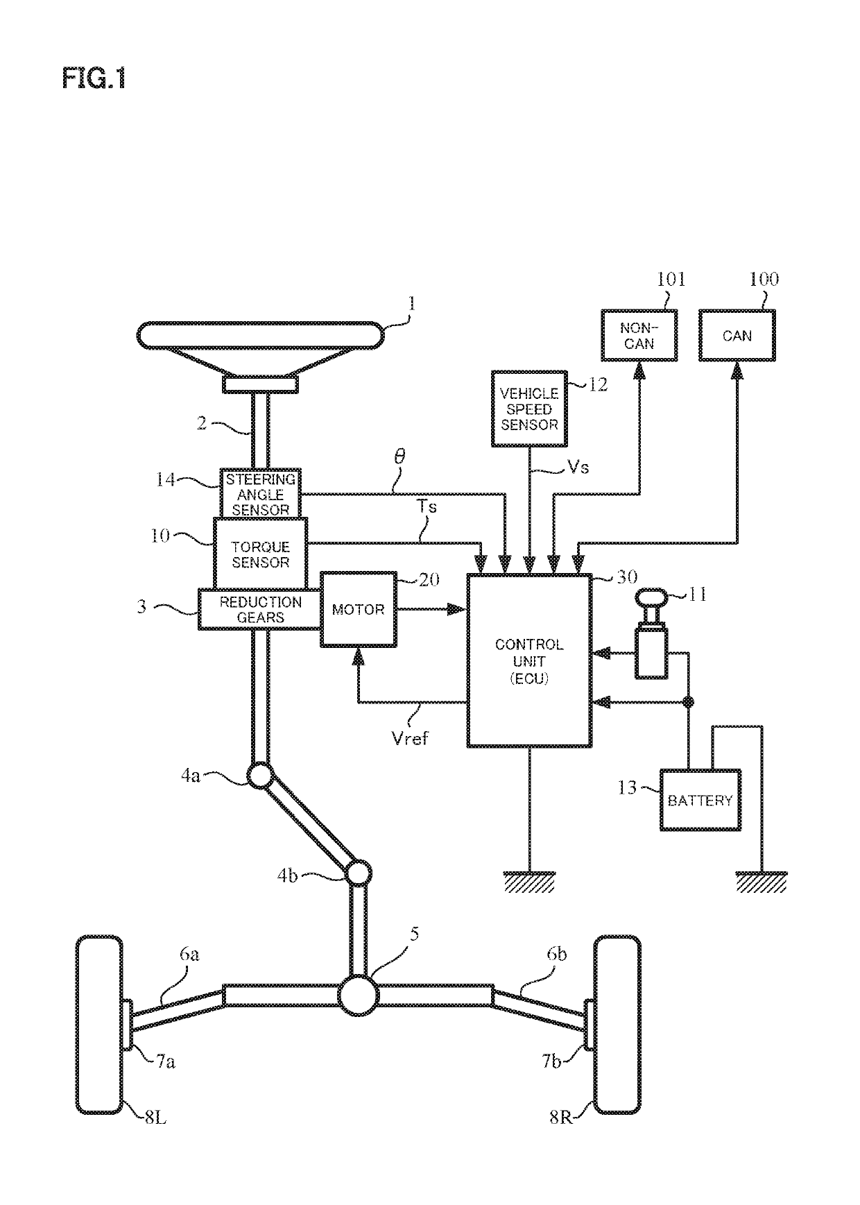
CROSS REFERENCE TO RELATED APPLICATIONS[0001]This application is a National Stage of International Application No. PCT / JP2016 / 061061 filed Apr. 5, 2016, claiming priority based on Japanese Patent Application No. 2015-080664 filed Apr. 10, 2015, the contents of all of which are incorporated herein by reference in their entirety.TECHNICAL FIELD[0002]The present invention relates to a motor control unit that controls a motor current flowing to a motor through a feedback mechanism on the basis of a current command value being a steering command, and in particular to a motor control unit that can change a characteristic of the feedback mechanism in real time, and an electric power steering apparatus equipped with the same.BACKGROUND ART[0003]An electric power steering apparatus (EPS) which assists and control a steering system of a vehicle by means of a rotational torque of a motor, applies a driving force of the motor as a steering assist torque (an assist torque) to a steering shaft or...

Claims


Application Information

Patent Timeline
Patent Type & Authority Patents(United States)
IPC IPC(8): B62D5/04H02P21/22B62D6/00B62D6/10
CPCH02P21/22B62D6/008B62D5/0481B62D5/0463B62D6/10
Inventor YOSHIDA, KEITAIMAMURA, YOUSUKE
Owner NSK LTD
Learn More