
Temperature-aware task scheduling and proactive power management

a task scheduling and power management technology, applied in the direction of multi-processor based energy comsumption reduction, multi-programming arrangements, instruments, etc., can solve the problems of increasing the cooling cost of the soc, preventing the soc from achieving the highest performance, and reducing the reliability and lifetime of the so

Active Publication Date: 2019-10-22
ADVANCED MICRO DEVICES INC
View PDF11 Cites 3 Cited by
  • Summary
  • Abstract
  • Description
  • Claims
  • Application Information

AI Technical Summary

Benefits of technology

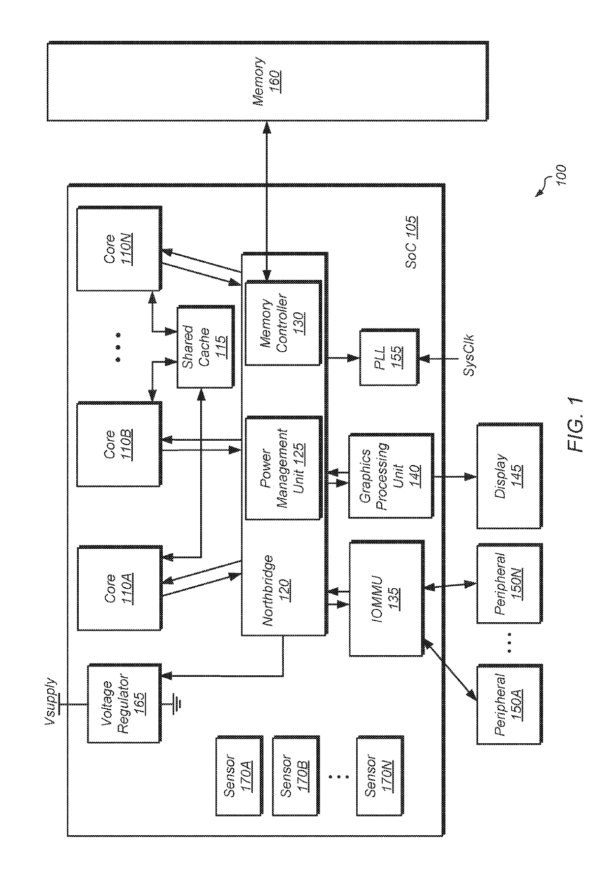
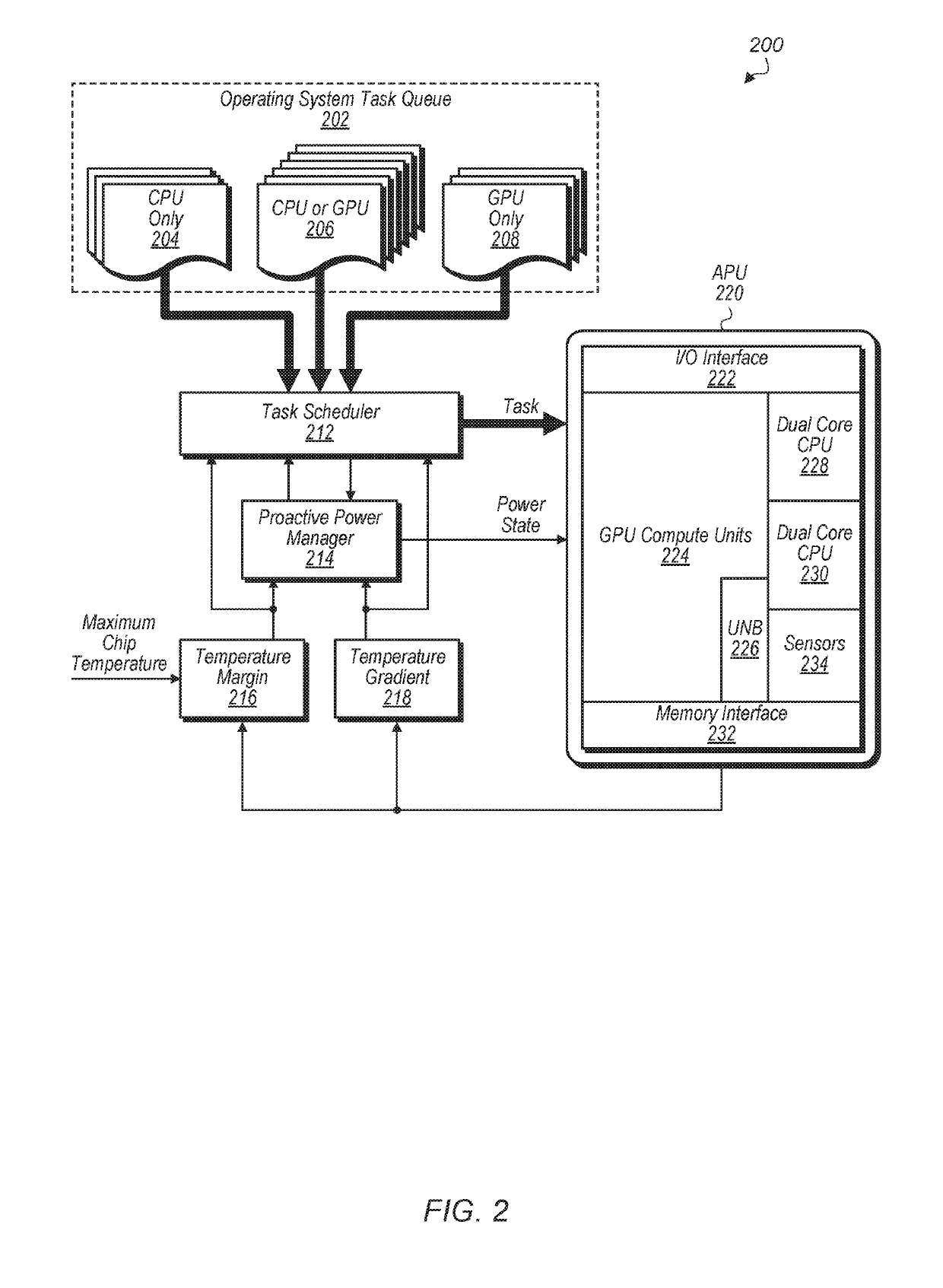
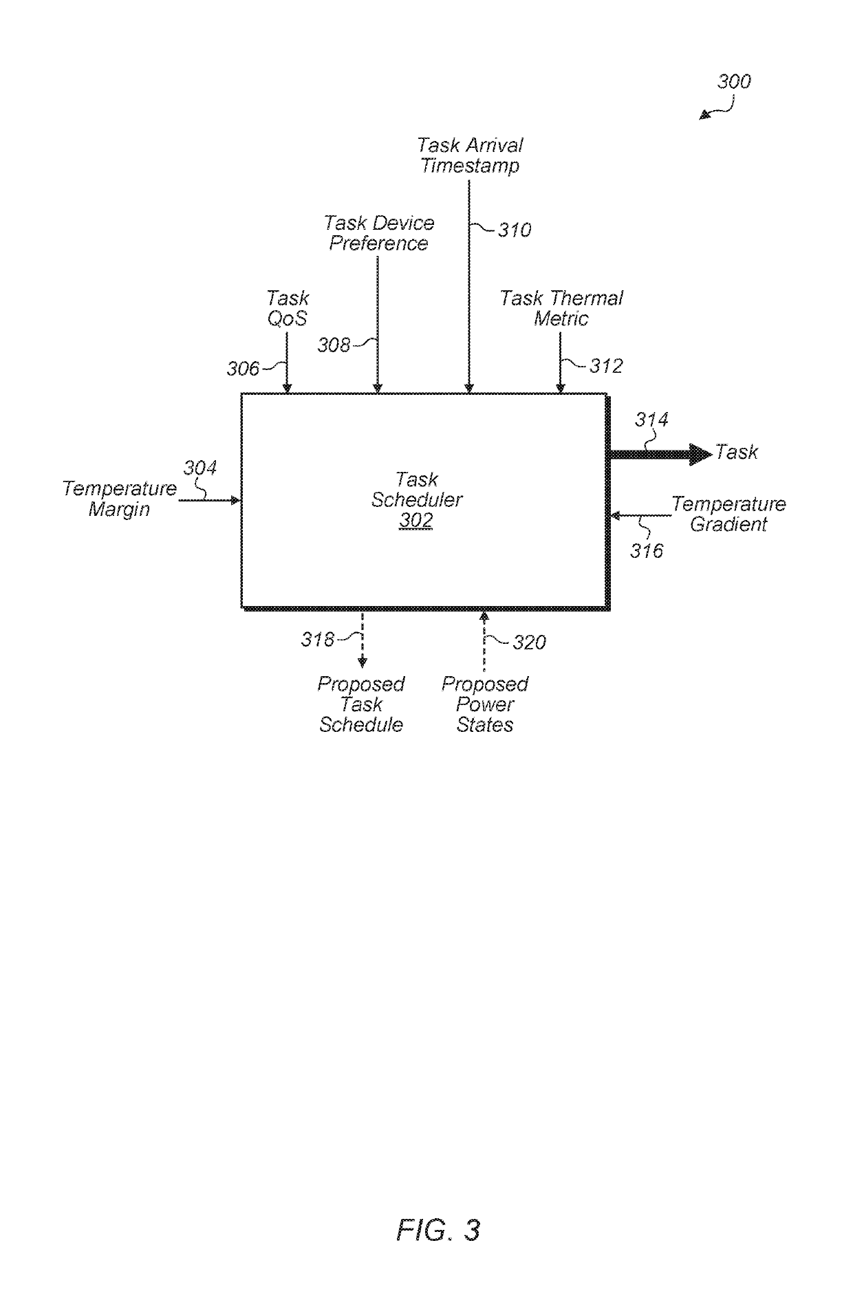
The patent describes a system and method for managing power consumption and temperature in computing systems. The technical effects of the invention include reducing non-uniform heat generation, preventing damage to the system, and improving performance and reliability. The invention uses a task queue and a power management unit to schedule tasks and manage the power states of processing units, ensuring that they operate efficiently and do not exceed their thermal limits. The system calculates a thermal metric for each task in the queue, taking into account the thermal gradient of each processing unit and the thermal margin available on each unit. The system assigns tasks to processing units based on their thermal metrics and thermal gradients, ensuring that they are performed efficiently and do not cause excessive heat generation. The invention is useful for managing power consumption and temperature in a wide range of computing systems.

Problems solved by technology

Also, even when the thermal limit is not exceeded, high operating temperatures can induce high leakage current and may cause a decrease in the reliability and lifetime of the SoC while also increasing the cooling cost of the SoC.
Additionally, non-uniform heat generation on an SoC may prevent the SoC from achieving its highest performance.

Method used


Image

  • Temperature-aware task scheduling and proactive power management
  • Temperature-aware task scheduling and proactive power management
  • Temperature-aware task scheduling and proactive power management

Examples


Embodiment Construction

[0012]In the following description, numerous specific details are set forth to provide a thorough understanding of the methods and mechanisms presented herein. However, one having ordinary skill in the art should recognize that the various embodiments may be practiced without these specific details. In some instances, well-known structures, components, signals, computer program instructions, and techniques have not been shown in detail to avoid obscuring the approaches described herein. It will be appreciated that for simplicity and clarity of illustration, elements shown in the figures have not necessarily been drawn to scale. For example, the dimensions of some of the elements may be exaggerated relative to other elements.

[0013]Systems, apparatuses, and methods for performing temperature aware task scheduling and proactive power management are contemplated. In one embodiment, a system-on-chip (SoC) includes at least a plurality of processing units, one or more memory devices, and ...


PUM


Abstract

Systems, apparatuses, and methods for performing temperature-aware task scheduling and proactive power management. A SoC includes a plurality of processing units and a task queue storing pending tasks. The SoC calculates a thermal metric for each pending task to predict an amount of heat the pending task will generate. The SoC also determines a thermal gradient for each processing unit to predict a rate at which the processing unit's temperature will change when executing a task. The SoC also monitors a thermal margin of how far each processing unit is from reaching its thermal limit. The SoC minimizes non-uniform heat generation on the SoC by scheduling pending tasks from the task queue to the processing units based on the thermal metrics for the pending tasks, the thermal gradients of each processing unit, and the thermal margin available on each processing unit.

Description

[0001]The invention described herein was made with government support under contract number DE-AC52-07NA27344 awarded by the United States Department of Energy. The United States Government has certain rights in the invention.BACKGROUNDDescription of the Related Art[0002]Managing power consumption in computing systems, integrated circuits (ICs), processors, and systems on chips (SoCs) is increasingly important. One of the objectives in operating an SoC is ensuring that the SoC's temperature does not exceed a thermal limit, above which the SoC cannot operate correctly or may even be damaged. Also, even when the thermal limit is not exceeded, high operating temperatures can induce high leakage current and may cause a decrease in the reliability and lifetime of the SoC while also increasing the cooling cost of the SoC. Additionally, non-uniform heat generation on an SoC may prevent the SoC from achieving its highest performance. Accordingly, intelligent thermal management schemes are i...

Claims


Application Information

Patent Timeline
Patent Type & Authority Patents(United States)
IPC IPC(8): G06F9/48G06F9/50G06F1/20G06F1/329
CPCG06F1/329G06F9/4893G06F9/5094G06F1/206Y02D10/24Y02D10/00
Inventor MAJUMDAR, ABHINANDANKOCOLOSKI, BRIAN J.PIGA, LEONARDOHUANG, WEIECKERT, YASUKO
Owner ADVANCED MICRO DEVICES INC
Learn More