
Display device and method of manufacturing the same

a technology of display panel and backlight unit, which is applied in the direction of optics, instruments, optical light guides, etc., can solve the problems of increased assembly costs, complicated assembly process, and misalignment between the coupling portions of the display panel and the backlight unit, so as to reduce the procedures required in the assembly process and cost, prevent degradation of luminance and defective screen images, and simplify the structure

Active Publication Date: 2019-10-22
LG DISPLAY CO LTD
View PDF2 Cites 0 Cited by
  • Summary
  • Abstract
  • Description
  • Claims
  • Application Information

AI Technical Summary

Benefits of technology

The technical effects of this patent are to provide a display device with a simple structure that reduces assembly processes and costs, and to reduce accumulative allowances in coupling portions of the display panel and backlight unit to prevent degradations in luminance and defective screen images due to misalignment. These improvements will increase consumer satisfaction and marketability.

Problems solved by technology

This consequently complicates the assembly process and increases assembly costs, both of which are problematic.
In particular, misalignment occurs in the coupling portions of the display panel and the backlight unit due to accumulated allowances of components.
This consequently causes luminance degradation and defective screen images in the display device, thereby lowering the marketability of the display device and the degree of commitment to images displayed on the screen.

Method used


Image

  • Display device and method of manufacturing the same
  • Display device and method of manufacturing the same
  • Display device and method of manufacturing the same

Examples


Embodiment Construction

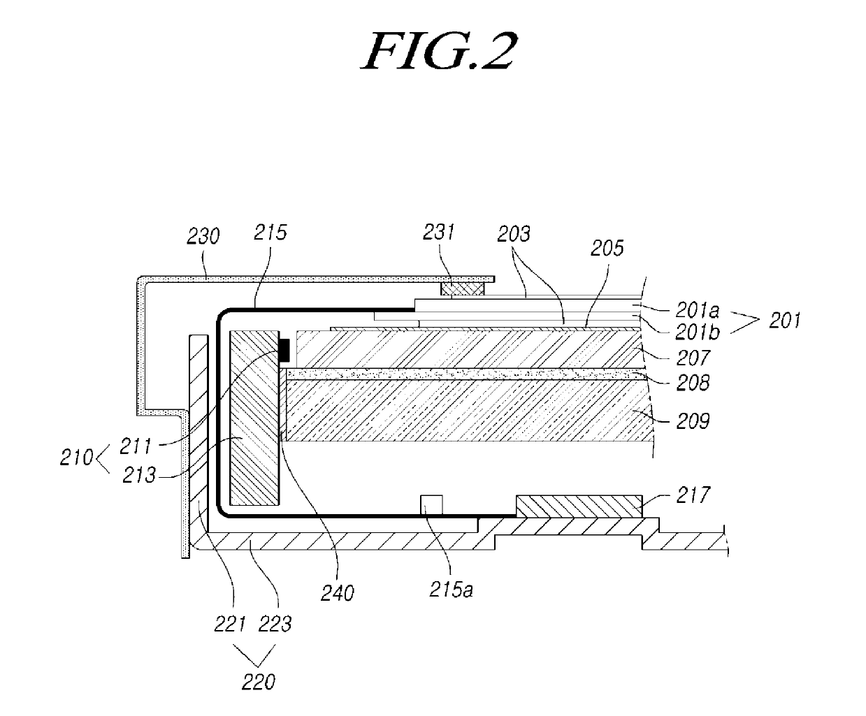
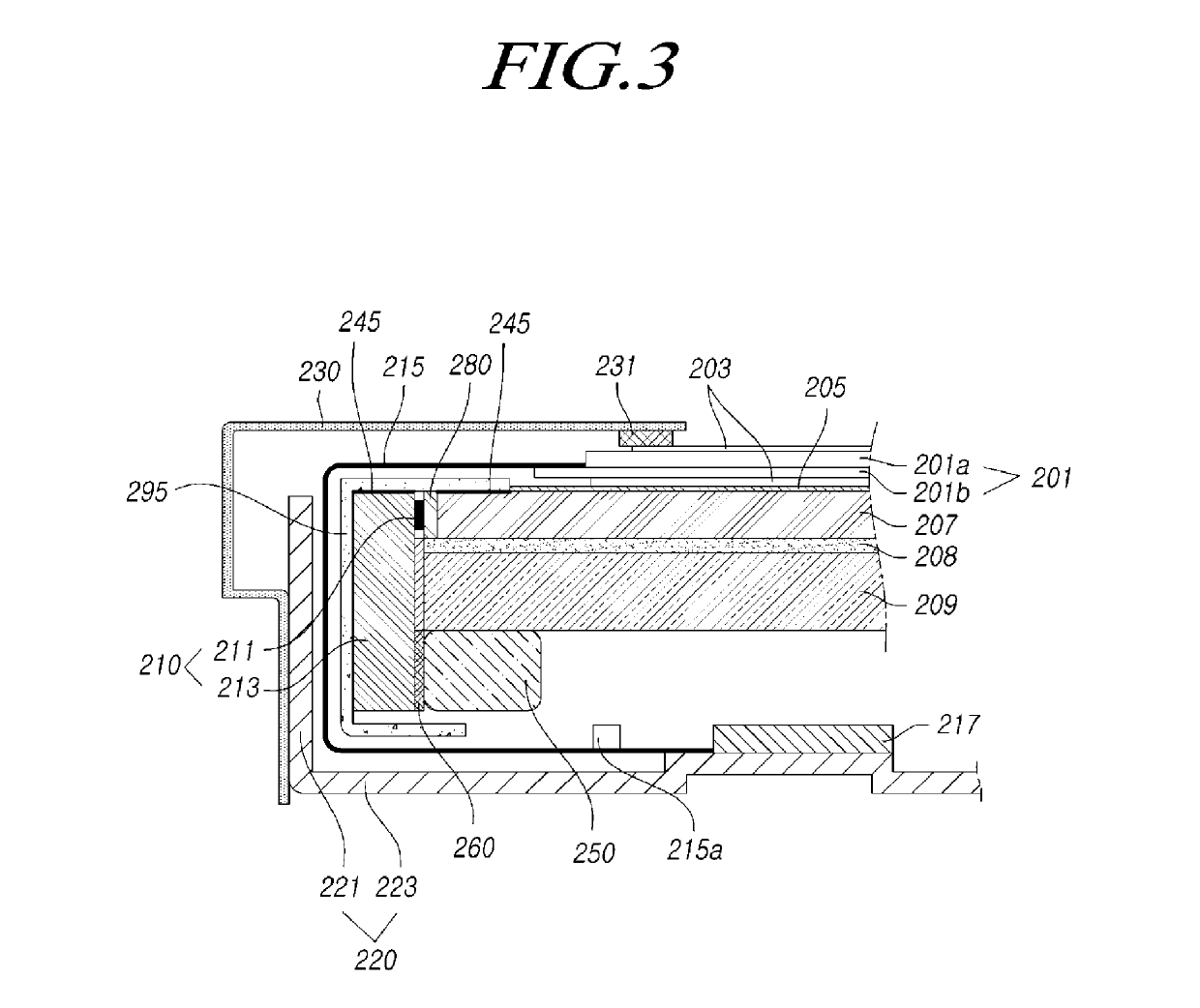
[0027]Reference will now be made in detail to some embodiments of the present disclosure, examples of that may be illustrated in the accompanying drawings. In the following description, when a detailed description of well-known functions or configurations related to this document is determined to unnecessarily cloud a gist of the inventive concept, the detailed description thereof will be omitted. The progression of processing steps and / or operations described is an example; however, the sequence of steps and / or operations is not limited to that set forth herein and may be changed as is known in the art, with the exception of steps and / or operations necessarily occurring in a particular order. Like reference numerals designate like elements throughout. Names of the respective elements used in the following explanations are selected only for convenience of writing the specification and may be thus different from those used in actual products.

[0028]In the description of embodiments, w...


PUM

PropertyMeasurementUnit
transparentaaaaaaaaaa
areaaaaaaaaaaa
luminanceaaaaaaaaaa

Abstract

A display device and a method of manufacturing the same are provided. A display device includes: a light guide plate on a rear surface of a display panel, the light guide plate being configured to direct light toward the display panel, a reflector on a rear surface of the light guide plate, the reflector being configured to reflect light from a rear of the light guide plate toward a front surface of the light guide plate, a back cover on a rear surface of the reflector, and a light-emitting diode array coupled to an edge of the back cover, the light-emitting diode array including: a printed circuit board, and a plurality of light-emitting diodes at a side surface of an edge of the light guide plate, the plurality of light-emitting diodes being configured to generate light, the plurality of light emitting diodes being attached to the printed circuit board.

Description

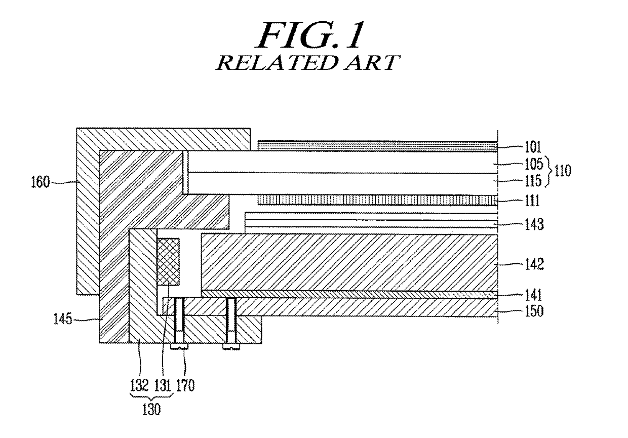
CROSS-REFERENCE TO RELATED APPLICATIONS[0001]This application claims the priority of Korean Application No. 10-2016-0176351, filed on Dec. 22, 2016, the entirety of which is hereby incorporated by reference.BACKGROUND[0002]1. Technical Field[0003]The present disclosure relates to a display device and a method of manufacturing the same.[0004]2. Discussion of the Related Art[0005]In general, research into flat panel display devices, such as liquid crystal display (LCD) devices, plasma display devices, field emission display devices, and organic light-emitting display devices, has been actively undertaken. Among such flat panel display devices, LCD devices and organic light-emitting display devices have recently come to prominence, due to advantages thereof, such as adaptability to mass production, easy implementation of driving units, as well as the realization of high resolution.[0006]FIG. 1 is a cross-sectional view schematically illustrating an LCD device of the related art.[0007]T...

Claims


Application Information

Patent Timeline
Patent Type & Authority Patents(United States)
IPC IPC(8): G02F1/1335G02F1/1333F21V8/00
CPCG02F1/133615G02F1/133608G02F1/133308G02F2001/133317G02F2202/28G02B6/0088G02B6/0091G02F1/133317G02B6/009G02F1/133314G02F2201/46
Inventor KIM, EUIJUNGKIM, JAEJUNLIM, GILYOUNGMIN, TAEBOKCHO, HYUNCHEOL
Owner LG DISPLAY CO LTD
Learn More