
Control of breathing during MRI-based procedures

a technology of breathing control and mri, applied in the direction of magnetic variable regulation, respiratory masks, radiation therapy, etc., can solve the problem of no special benefit in reducing the number of scans performed, and achieve the effect of preventing leakag

Active Publication Date: 2019-10-08
ELEKTA AB
View PDF13 Cites 1 Cited by
  • Summary
  • Abstract
  • Description
  • Claims
  • Application Information

AI Technical Summary

Benefits of technology

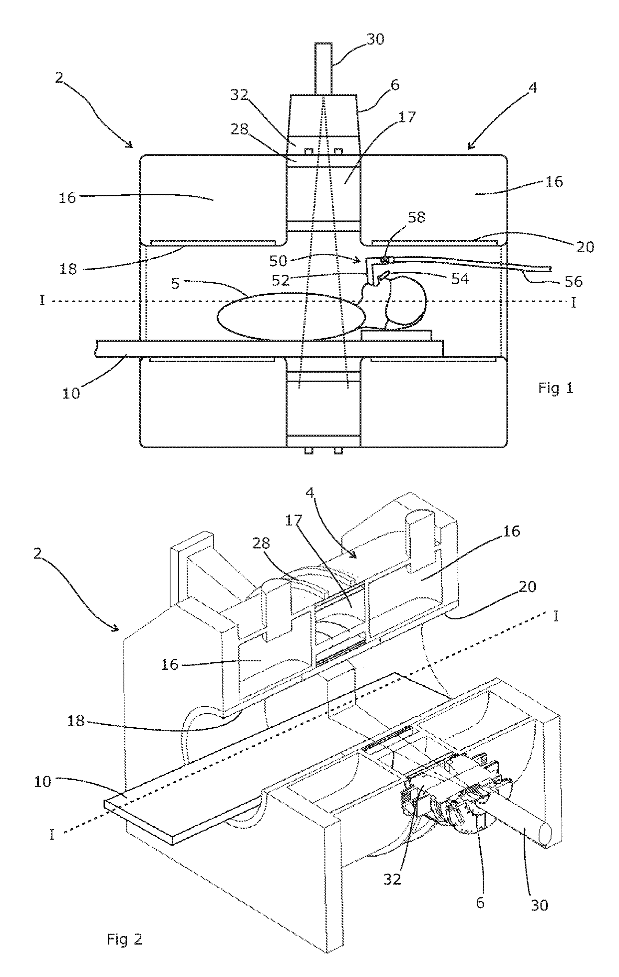
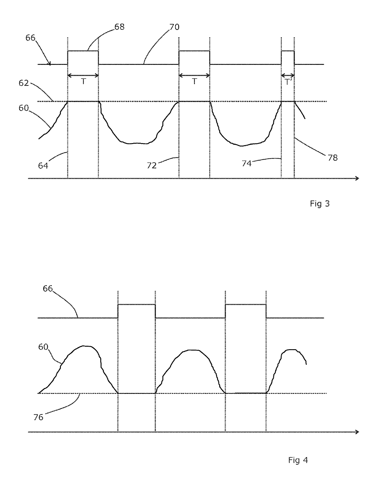
[0009]The present invention is based on the realisation that the valve of the ABC device can be driven by an output derived from the navigator channel (or another fast-acquisition output) of the MRI scanner, rather than by inference from the measured flow rate. This has the advantage that the MRI output can yield a first-hand measurement of the diaphragm position or the tumour position. The computed lung volume obtained from a pneumotachograph is subject to drift over time for a variety of reasons, so a direct measurement of the anatomy will be more reliable. Where the MRI scanner is integrated with a radiotherapy device, the MRI data can be used to trigger the enforced breath-hold by the ABC, and the radiotherapy delivered while the ABC valve is shut. If the MRI data pertains to the actual position of the tumour, then the ABC device will (in effect) hold the tumour at a precise and reproducible point for treatment.
[0012]This functionality can be used to improve either MRI scanning techniques, or radiotherapy techniques. Generally, the non-ionising nature of MRI scanning means that there is no especial benefit in reducing the number of scans performed. Therefore, it will often be easier to scan the patient continuously (without an ABC) and retrospectively select k-space data which the navigator channel indicates were timed to share a common breathing phase. However, where the MRI scan is a preliminary step prior to radiotherapy, such as the acquisition of image data for treatment planning, it will be advantageous to obtain an image of the anatomy in the position in which it will be treated.
[0015]The breath control device can comprise a face mask attachable to a patient, or the like. Other forms include a tube through which the patient can breathe, often combined with a nasal clip to prevent leakage.

Problems solved by technology

Generally, the non-ionising nature of MRI scanning means that there is no especial benefit in reducing the number of scans performed.

Method used


Image

  • Control of breathing during MRI-based procedures
  • Control of breathing during MRI-based procedures

Examples


Embodiment Construction

[0021]FIGS. 1 and 2 show a system 2 according to embodiments of the present invention, comprising a radiotherapy apparatus 6 and a magnetic resonance imaging (MRI) apparatus 4. A patient 5 is present in FIG. 1 and shown in part, but is not present in FIG. 2.

[0022]The system includes a couch 10, for supporting the patient 5 in the apparatus. The couch 10 is movable along a horizontal, translation axis (labelled “I”), such that a patient resting on the couch is moved into the radiotherapy and MRI apparatus. In one embodiment, the couch 10 is rotatable around a central vertical axis of rotation, transverse to the translation axis, although this is not illustrated. The couch 10 may form a cantilever section that projects away from a support structure (not illustrated). In one embodiment, the couch 10 is moved along the translation axis relative to the support structure in order to form the cantilever section, i.e. the cantilever section increases in length as the couch is moved and the ...


PUM


Abstract

The valve of an active breathing control (ABC) device can be driven by the output of the navigator channel of the MRI scanner, rather than by inference from a measured breath flow rate. Where the MRI scanner is integrated with a radiotherapy device, the MRI data can be used to trigger the enforced breath-hold by the ABC, and the radiotherapy delivered while the ABC valve is shut. If the MRI data pertains to the actual position of the tumor, then the ABC device will (in effect) hold the tumor at a precise and reproducible point for treatment.

Description

CROSS-REFERENCE TO RELATED PATENT APPLICATIONS[0001]This application is a national phase of International Application No. PCT / EP2015 / 062942, filed on Jun. 10, 2015, which claims priority to United Kingdom Patent Application No. 1411246.0, filed on Jun. 25, 2014. The contents of the above-referenced applications are expressly incorporated herein by reference in their entireties.FIELD OF THE INVENTION[0002]The present invention relates to the control of breathing during medical procedures that include an MRI-based component.BACKGROUND ART[0003]MRI scanning processes are sensitive to movement of the patient's anatomy that is being scanned. It takes time to acquire a complete k-space data set (the Fourier data set from which an MRI image is computed), typically a minute or so, and any movement will result in different parts of the sampled k-space data set being obtained with the patient's anatomy in different positions. This inconsistency in the data set will create motion artefacts in ...

Claims


Application Information

Patent Timeline
Patent Type & Authority Patents(United States)
IPC IPC(8): A61B5/055G01R33/28A61M16/00A61B5/113A61M16/06A61N5/10G01R33/565G01R33/567A61M16/20A61B5/00G01R33/48
CPCG01R33/28A61B5/7292A61M16/021A61B5/055A61B5/113A61M16/202G01R33/4812G01R33/56509A61M16/06G01R33/5676A61N5/1068A61M2205/33A61N2005/1055A61B5/4887A61M16/00A61B5/0515A61B5/0522A61N5/00A61N5/1048G01R33/56G01R33/567
Inventor BROWN, KEVIN
Owner ELEKTA AB
Learn More