Engine
a technology for engines and air intake chambers, applied in the field of engines, can solve the problems of increased oil consumption, excessive amount of oil entering the air intake chamber, leakage of cylinder head covers, etc., and achieve the effects of reducing oil consumption, hardly vibrating, and increasing rigidity of the bottom wall of the air intake chamber
- Summary
- Abstract
- Description
- Claims
- Application Information
AI Technical Summary
Benefits of technology
Problems solved by technology
Method used
Image
Examples
first embodiment
[0036]An outline of the engine is as follows.
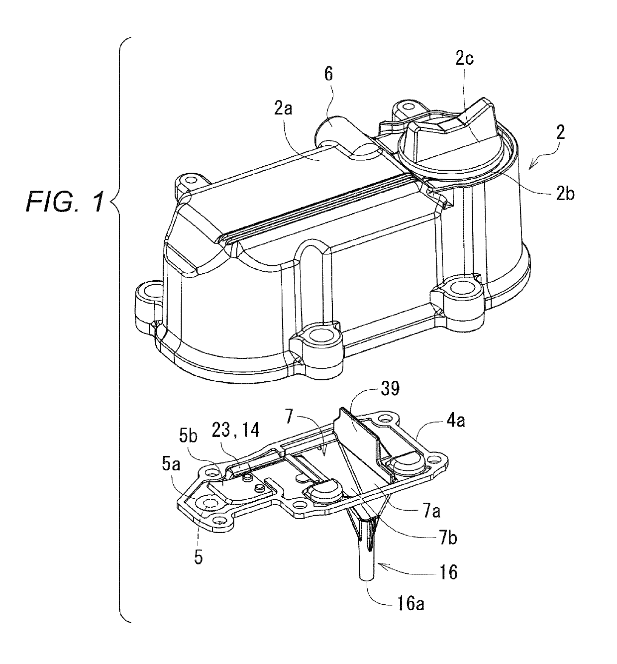
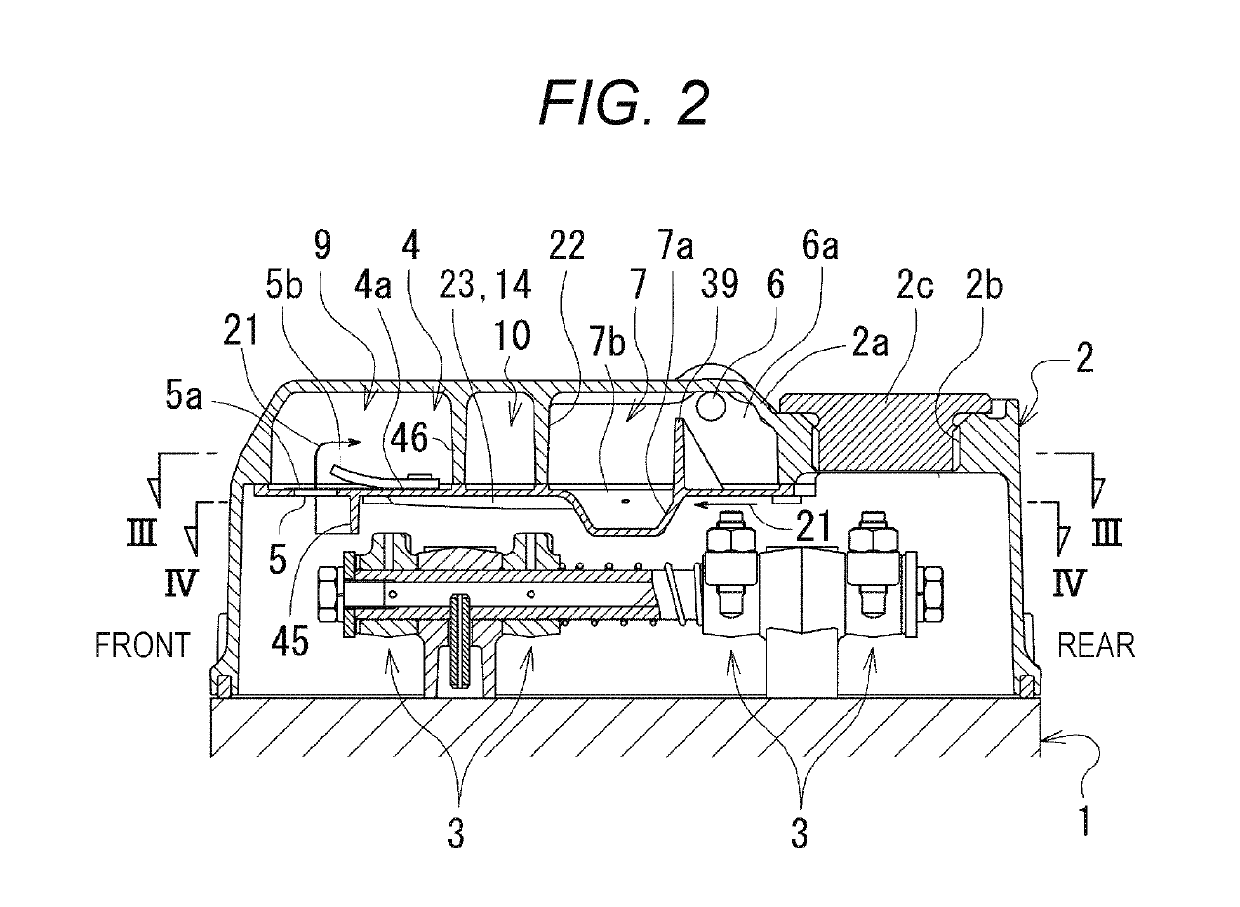
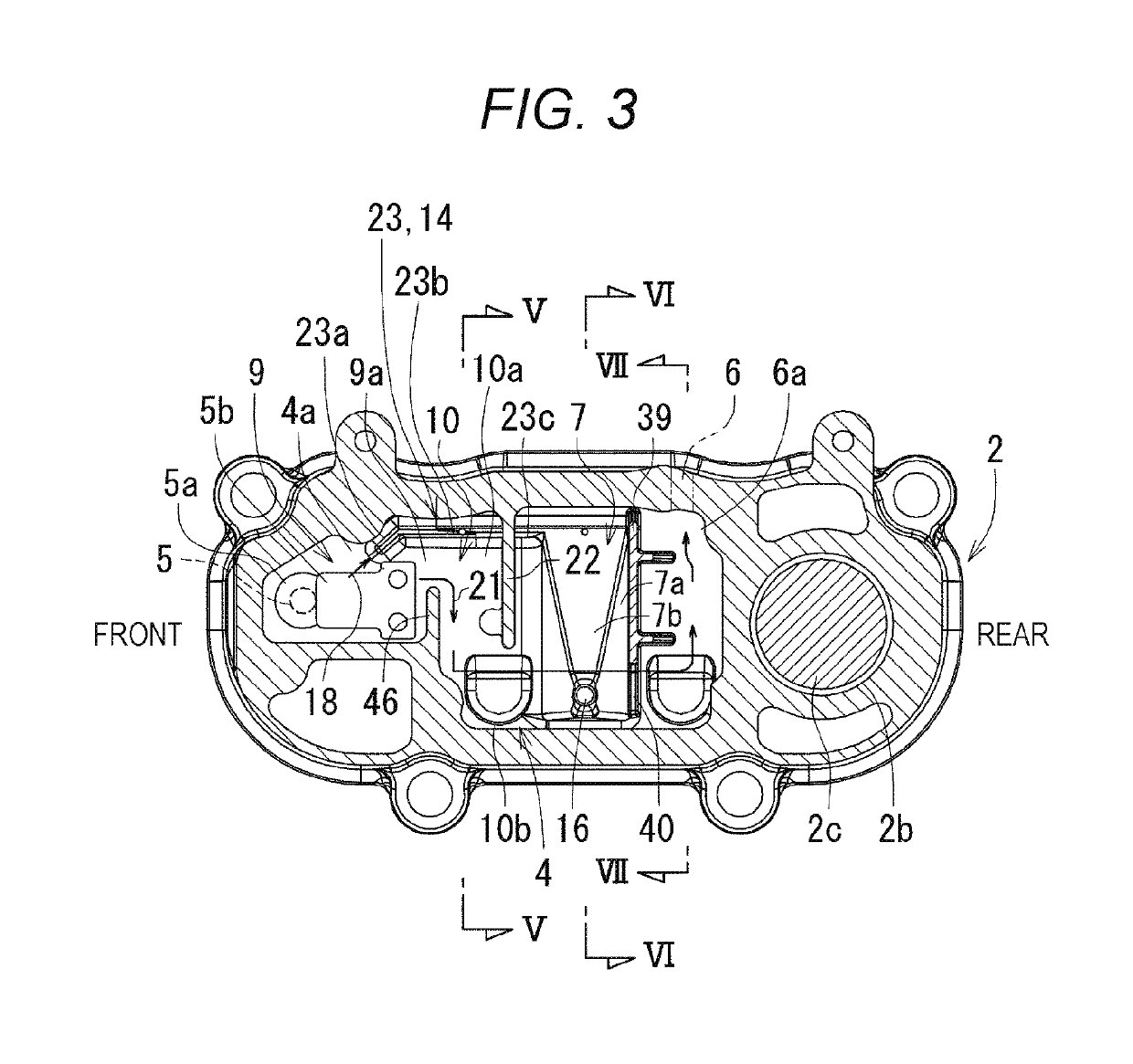
[0037]As shown in FIG. 2, a cylinder head (1) is mounted above a cylinder block (not shown), and a cylinder head cover (2) is mounted above the cylinder head (1). As a front-rear direction is defined by the installation direction of a crank shaft (not shown), its one side is defined as the front and another side is defined as the rear.
[0038]An oil pan (not shown) is mounted below the cylinder block (not shown).
[0039]A swirl chamber (not shown) is formed in the cylinder head (1), and fuel is injected into the swirl chamber (not shown) from a fuel injection pump (not shown) via a fuel injection pipe (not shown) and a fuel injection nozzle (not shown).
[0040]As shown in FIG. 7, a valve device (32) for intake air and exhaust air is housed in the cylinder head cover (2), and the valve device (32) is driven by a valve driving device (33). The valve driving device (33) is provided with a valve driving cam (not shown), a tappet (not shown), a pus...
second embodiment
[0097]Next, an engine shown in FIGS. 15 to 23 is described.
[0098]In the engine according to the second embodiment, an oil discharging guide chamber (7) has a baffle plate (8) and this configuration is different from the engine according to the first embodiment. Other configurations are similar to those in the engine according to the first embodiment.
[0099]As shown in FIGS. 16A and 16C, the oil discharging guide chamber (7) has the baffle plate (8) which receives the separated oil (18) splashed up from the pipe inlet (16c) of the oil discharging pipe (16) due to the backflow of the separated oil (18).
[0100]According to the configuration described above, even when the separated oil (18) in the oil storing part (17) is splashed up from the pipe inlet (16c) to the oil discharging guide chamber (7) due to the backflow, since the separated oil (18) is received by the baffle plate (8) and is hardly diffused in the oil discharging guide chamber (7), the separated oil (18) hardly flows out ...
PUM
 Abstract
Description
Claims
Application Information
 - R&D
- Intellectual Property
- Life Sciences
- Materials
- Tech Scout
- Unparalleled Data Quality
- Higher Quality Content
- 60% Fewer Hallucinations
Browse by: Latest US Patents, China's latest patents, Technical Efficacy Thesaurus, Application Domain, Technology Topic, Popular Technical Reports.
© 2025 PatSnap. All rights reserved.Legal|Privacy policy|Modern Slavery Act Transparency Statement|Sitemap|About US| Contact US: help@patsnap.com


