
Optogenetic tool for multiple and independently addressing of patterned optical windows

a technology of optical windows and optogenetic tools, applied in the field of multi-point light delivery devices, can solve the problems of limited localization of recording sites, poor spatial selectivity of optical excitation, and high spatial resolution of activity detection

Active Publication Date: 2019-09-03
FOND INST ITAL DI TECH +1
View PDF5 Cites 2 Cited by
  • Summary
  • Abstract
  • Description
  • Claims
  • Application Information

AI Technical Summary

Benefits of technology

The patent aims to reduce the noise generated when electrodes and light emitting elements are placed on the same or adjacent shafts, which can affect the accuracy of data collected through a neural interface device. The technical effect can thus improve the accuracy of data collection and minimize the impact of the Becquerel effect on signals.

Problems solved by technology

However, in standard devices light is delivered into the brain by means of a single optical fiber able to deliver light only to a single, fixed area of the brain.
The high number of recording channels is thus not accompanied by comparable amount of light delivery points, creating a mismatch in which electrical activity can be detected with high spatial resolution, while the optical excitation has a poor spatial selectivity.
However, this layout limits localization of the recording sites to a small brain region near the tip of the fiber, with the effective distance determined by the light intensity.
The excited brain volume can again he expanded by increasing the emitted optical power, but increasing light intensity to reach distant recording sites will lead to increased electrical artifacts on the closer sites.
It is therefore evident that optrodes based on a single light-emitting point source have significant limitations for the integration of multiple-site recording systems.
Both strategies allow an improved distribution of light intensity in the investigated brain volume, but this is obtained by recurring to multiple light sources and complicated and cumbersome coupling strategies.

Method used


Image

  • Optogenetic tool for multiple and independently addressing of patterned optical windows
  • Optogenetic tool for multiple and independently addressing of patterned optical windows
  • Optogenetic tool for multiple and independently addressing of patterned optical windows

Examples


Embodiment Construction

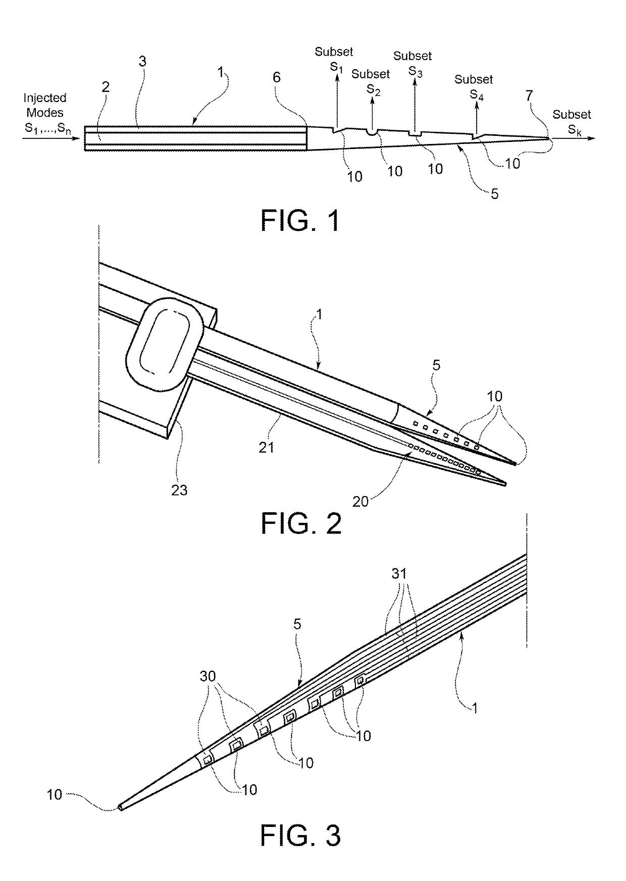
[0027]With reference to FIG. 1, a multi-point light delivering device according to the invention is shown. This device comprises a waveguide 1, a section of which is shown in FIG. 1. This waveguide is an optical fiber conventionally comprising a core 2 and a cladding 3. The waveguide 1 extends along a longitudinal axis, between a distal end (not shown in FIG. 1), which is adapted to be coupled to a light source, and a proximal end 5. Light injected by the light source is carried by the waveguide 1 along its longitudinal axis, and out-coupled by the proximal end 5 of the waveguide 1. The proximal end 5 is as tapered region of the waveguide 1, extending between a taper base 6 adjacent to the rest of the waveguide 1, and a taper tip 7. This tapered region has preferably a taper angle between 1° and 10°, preferably between 3° and 6°. The tapered region 5 of the waveguide is coated with a reflective coating. A plurality of optical windows 10 are formed along the tapered region 5.

[0028]Th...


PUM


Abstract

A multi-point light-delivering device, comprising a waveguide carrying light along a longitudinal axis and including multiple optical windows, through which the carried light is out-coupled from the waveguide. The waveguide comprises a tapered region along which the optical windows are distributed, wherein each optical window out-couples a specific subset of propagating modes of the carried light, to which the optical window is matched.

Description

STATEMENT AS TO RIGHTS TO INVENTIONS MADE UNDER FEDERALLY SPONSORED RESEARCH OR DEVELOPMENT[0001]This research was made, in part, with government support under NIH Grants R01 NSO46579 and F31 MH093026 awarded by the National Institutes of Health; the United States Government has certain rights in the invention.BACKGROUND[0002]The present invention relates to a multi-point light-delivering device, comprising a waveguide carrying light along a longitudinal axis and including multiple optical windows, through Which the carried light is out-coupled from the waveguide.[0003]Such a device may be used as an optogenetic tool to be exploited both for in-vitro experiments with neuronal tissues and for in-vivo experiments or medical applications, in such experiments, specific neurons are targeted to express light-sensitive proteins or are exposed to light-sensitive compounds. Examples of light-sensitive proteins include proteins that alter the electrical and biochemical state of the neuron or ...

Claims


Application Information

Patent Timeline
IPC IPC(8): A61B1/07A61B5/00A61N5/06G02B6/14G02B6/26A61B18/22
CPCG02B6/14A61N5/062A61B18/22A61B5/0084A61B1/07G02B6/262A61N5/0622A61B2018/2261A61B2018/2255A61B2562/0233A61N2005/063
Inventor PISANELLO, FERRUCCIOMARTIRADONNA, LUIGISILEO, LEONARDOOLDENBURG, IAN ANTONPISANELLO, MARCOSABATINI, BERNARDO LUISASSAD, JOHN ABRAHAMDE VITTORIO, MASSIMO
Owner FOND INST ITAL DI TECH
Learn More