
Systems and methods for electrostatic trapping of contaminants in cryogenic refrigeration systems

a technology of electrostatic trapping and cryogenic refrigeration, which is applied in the direction of refrigeration components, refrigeration machines, light and heating apparatus, etc., can solve the problems of increasing contaminants, increasing the surface area available for bonding, and increasing the contaminant removal efficiency of the trap. , to achieve the effect of increasing the surface area available for bonding, and improving the contaminant removal efficiency of the trap

Active Publication Date: 2019-08-13
D WAVE SYSTEMS INC
View PDF65 Cites 2 Cited by
  • Summary
  • Abstract
  • Description
  • Claims
  • Application Information

AI Technical Summary

Benefits of technology

The electrostatic cryogenic cold trap significantly reduces the frequency of plugging events by effectively removing contaminants, allowing for continuous operation of dilution refrigeration systems and minimizing the need for frequent maintenance, thereby enhancing the reliability and availability of cryogenic refrigeration systems.

Problems solved by technology

For instance, environments of extreme heat can cause even the strongest and most solid materials to melt away or disperse as gas.
The pumps and compressors used are large, expensive, noisy, in need of periodic maintenance, and they inevitably add contaminants, such as air (i.e., nitrogen, oxygen, carbon dioxide, argon, etc.) to the helium.
These contaminants typically have higher freezing points than the helium and so may solidify in the helium fluid channels, creating blockages.
Such blockages may plug fine capillaries in the dilution refrigerator, causing problems with reliability.
The procedure of warming and subsequently cooling back down to operating temperatures can take several days.
Filters and cold traps can be used to reduce the frequency of plugging by removing contaminants from the helium, but current filters and traps are of limited effectiveness.
Thus, plugging due to contaminants, such as, nitrogen, oxygen, carbon dioxide, and argon remains a serious technical challenge in cryogenic refrigeration technology affecting refrigeration system performance and availability.

Method used


Image

  • Systems and methods for electrostatic trapping of contaminants in cryogenic refrigeration systems
  • Systems and methods for electrostatic trapping of contaminants in cryogenic refrigeration systems

Examples


Embodiment Construction

[0022]In the following description, some specific details are included to provide a thorough understanding of various disclosed embodiments. One skilled in the relevant art, however, will recognize that embodiments may be practiced without one or more of these specific details, or with other methods, components, materials, etc. In other instances, well-known structures associated with refrigeration systems, such as heat exchangers, impedances, and control systems including microprocessors, heat switches, drive circuitry and nontransitory computer- or processor-readable media such as nonvolatile memory for instance read only memory (ROM), electronically erasable programmable ROM (EEPROM) or FLASH memory, etc., or volatile memory for instance static or dynamic random access memory (ROM) have not been shown or described in detail to avoid unnecessarily obscuring descriptions of the embodiments of the present systems and methods.

[0023]Unless the context requires otherwise, throughout th...


PUM


Abstract

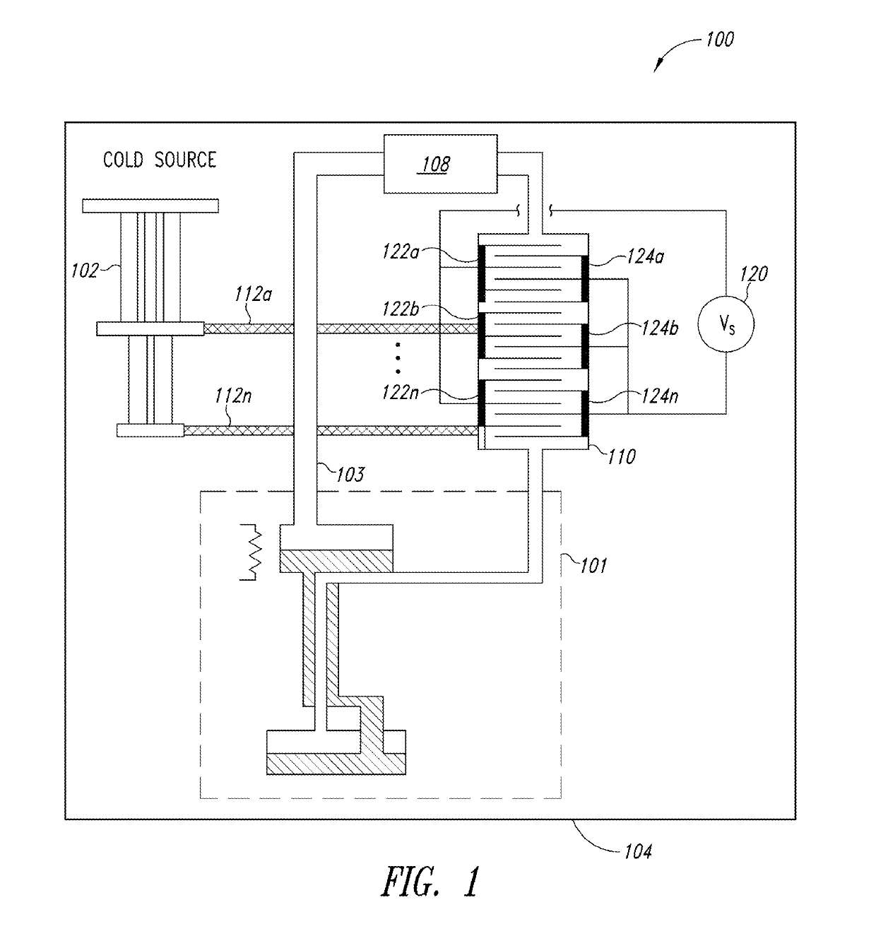
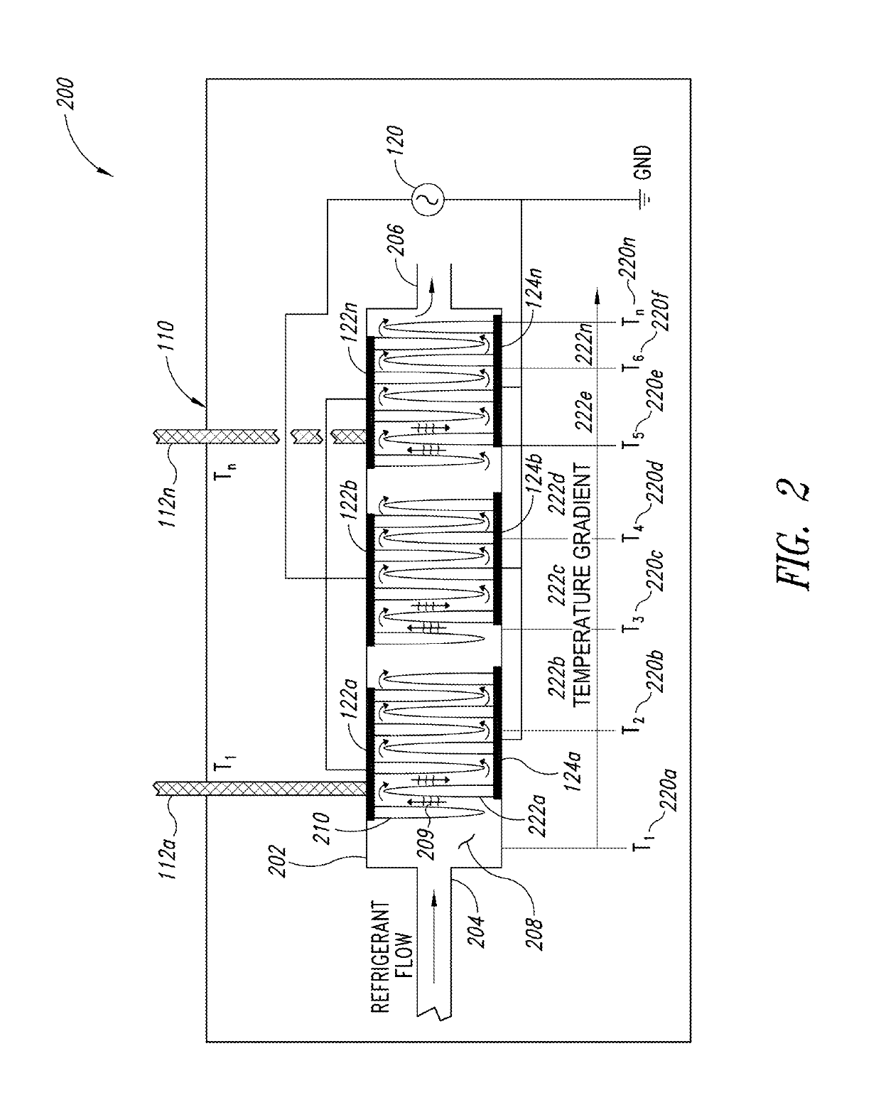
Systems and methods for improving the performance of dilution refrigeration systems are described. Electrostatic cryogenic cold traps employed in the helium circuit of a dilution refrigerator improve the removal efficiency of contaminants from the helium circuit. An ionization source ionizes at least a portion of a refrigerant that includes helium and number of contaminants. The ionized refrigerant passes through an electrostatic cryogenic cold trap that includes a number of surfaces at one or more temperatures along at least a portion of the fluid passage between the cold trap inlet and the cold trap outlet. A high voltage source coupled to the surfaces to causes a first plurality of surfaces to function as electrodes at a first potential and a second plurality of surfaces to function as electrodes at a second potential. As ionized contaminants release their charge on the electrodes, the contaminants bond to the electrodes.

Description

BACKGROUND[0001]Field[0002]The present systems and methods generally relate to cryogenic refrigeration technology.[0003]Refrigeration[0004]Temperature is a property that can have a great impact on the state and evolution of a physical system. For instance, environments of extreme heat can cause even the strongest and most solid materials to melt away or disperse as gas. Likewise, a system that is cooled to cryogenic temperatures may enter into a regime where physical properties and behavior differ substantially from what is observed at room temperature. In many technologies, it can be advantageous to operate in this cryogenic regime and harness the physical behaviors that are realized at low temperatures. The various embodiments of the systems, methods and apparatus described herein may be used to provide and maintain the cryogenic environments necessary to take advantage of the physics at cold temperatures.[0005]Throughout this specification and the appended claims, the term “cryog...

Claims


Application Information

Patent Timeline
Patent Type & Authority Patents(United States)
IPC IPC(8): B03C3/41F25B9/14B03C3/45F25B43/00
CPCF25B43/00B03C3/41F25B9/145B03C3/45B03C2201/06
Inventor UCHAYKIN, SERGEY
Owner D WAVE SYSTEMS INC
Learn More