
Alternating pump gaps

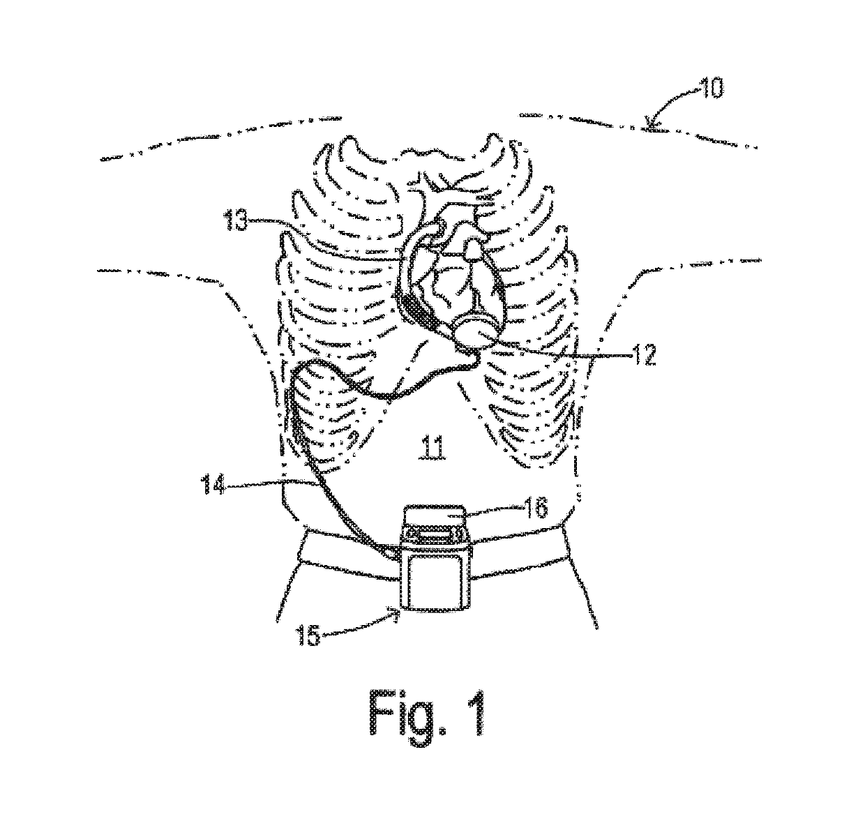
a technology of alternating pump and gap, which is applied in the direction of machines/engines, prosthesis, liquid fuel engines, etc., can solve the problems of high probability of thrombosis in the bearing or to elevated hemolysis, insufficient washout, and compromise the hydrodynamic bearing performance and pump efficiency, so as to achieve the effect of increasing the washout ra

Active Publication Date: 2019-08-06
TC1 LLC
View PDF595 Cites 13 Cited by
  • Summary
  • Abstract
  • Description
  • Claims
  • Application Information

AI Technical Summary

Benefits of technology

This patent text describes a blood pump system that can adjust the size of gaps between the impeller and the housing to control the washout rate. This system includes a position control mechanism that moves the impeller in an axial direction to change the gap sizes. The technical effect of this invention is to improve the performance of blood pumps by controlling blood flow and washout rate.

Problems solved by technology

A small gap may lead to the high probability of the thrombus formation in the bearing or to elevated hemolysis due to excessive shear stress.
Likewise, a large gap can compromise the hydrodynamic bearing performance and the pump efficiency.
However, such a design usually requires a small bearing gap to provide sufficient hydrodynamic bearing stiffness to maintain impeller levitation and prevent contacts between impeller and the pump housing.
Such a small gap may result in an insufficient washout and vulnerability to blood clotting thus compromising hemocompatibility.
A drawback of such designs is that the impeller starts to tilt when the pump flow rate increases.
This impeller position shift under low pressure conditions across the narrow gap creates blood flow stasis, which in turn leads to thrombus formation on the bearing surfaces.
However, the magnetic bearing solution increases the size of the pump and complexity of the system.

Method used


Image

  • Alternating pump gaps
  • Alternating pump gaps
  • Alternating pump gaps

Examples


Embodiment Construction

[0042]Reference will now be made in detail to the preferred embodiments of the invention, examples of which are illustrated in the accompanying drawings. While the invention will be described in conjunction with the preferred embodiments, it will be understood that they are not intended to limit the invention to those embodiments. On the contrary, the invention is intended to cover alternatives, modifications and equivalents, which may be included within the spirit and scope of the invention as defined by the appended claims.

[0043]For convenience in explanation and accurate definition in the appended claims, the terms “up” or “upper”, “down” or “lower”, “inside” and “outside” are used to describe features of the present invention with reference to the positions of such features as displayed in the figures.

[0044]In many respects the modifications of the various figures resemble those of preceding modifications and the same reference numerals followed by subscripts “a”, “b”, “c”, and ...


PUM


Abstract

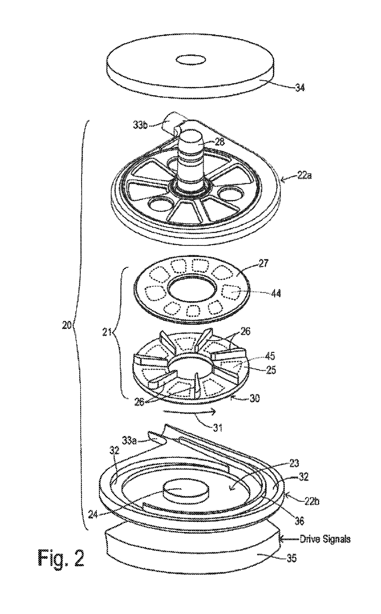
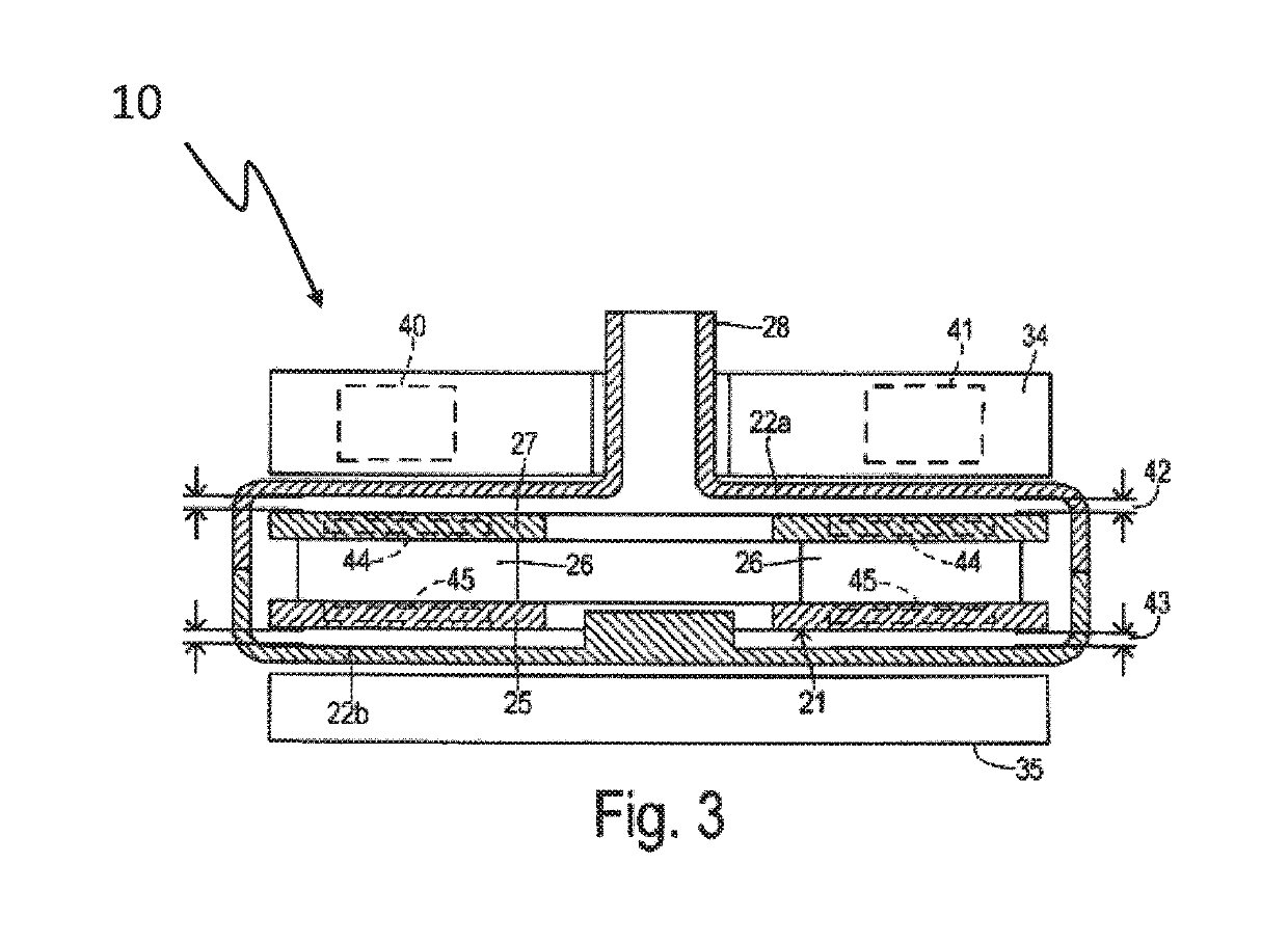
A blood pump system includes a pump housing and an impeller for rotating in a pump chamber within the housing. The impeller has a first side and a second side opposite the first side. The system includes a stator having drive coils for applying a torque to the impeller and at least one bearing mechanism for suspending the impeller within the pump chamber. The system includes a position control mechanism for moving the impeller in an axial direction within the pump chamber to adjust a size of a first gap and a size of a second gap, thereby controlling a washout rate at each of the first gap and the second gap. The first gap is defined by a distance between the first side and the housing and the second gap is defined by a distance between the second side and the pump housing.

Description

CROSS-REFERENCE TO RELATED APPLICATIONS[0001]This application claims priority to U.S. Provisional Application No. 62 / 115,318, filed Feb. 12, 2015 and entitled “ALTERNATING PUMP GAPS,” which is hereby incorporated by reference in its entirety.BACKGROUND OF THE INVENTION[0002]The present invention relates in general to pumping devices, and more specifically, to improved blood pumps with levitated impellers and methods for their control.[0003]Mechanical circulatory support (MCS) devices are commonly used for treating patients with heart failure. One exemplary type of MCS device is a centrifugal flow blood pump. Many types of circulatory support devices are available for either short term or long term support for patients having cardiovascular disease. For example, a heart pump system known as a left ventricular assist device (LVAD) can provide long term patient support with an implantable pump associated with an externally-worn pump control unit and batteries. The LVAD improves circula...

Claims


Application Information

Patent Timeline
Patent Type & Authority Patents(United States)
IPC IPC(8): F04D13/06A61M1/10F04D29/047F04D29/048A61M1/12A61M60/232A61M60/237A61M60/422A61M60/538A61M60/82A61M60/824
CPCF04D13/064A61M1/1013A61M1/1015A61M1/1029A61M1/1031A61M1/1086F04D29/047F04D29/048F04D13/0666A61M2205/3334A61M1/101A61M1/1012A61M1/1017A61M1/122F04D13/0646A61M60/82A61M60/824A61M60/422A61M60/232A61M60/237A61M60/538A61M60/178
Inventor YANAI, MASAMICHIYU, SHUNZHOUZHANG, TAO
Owner TC1 LLC
Learn More