Waveform enhanced reflection and margin boundary characterization for ultrasound tomography

a technology of ultrasound tomography and enhanced reflection, which is applied in image enhancement, instruments, applications, etc., can solve the problems of loss of signal coherency, limitations of imaging dense breasts, and current methods for ultrasound reflection imaging that are less than ideal in some respects, and achieve enhanced reflection images of a volume of tissue. , the effect of high spatial resolution

Active Publication Date: 2019-08-06
DELPHINUS MEDICAL TECH
View PDF16 Cites 1 Cited by
  • Summary
  • Abstract
  • Description
  • Claims
  • Application Information

AI Technical Summary

Benefits of technology

[0007]Recognizing a need for high-quality imaging of tissue, the present disclosure provides improved methods and systems for enhancing a reflection image of a volume of tissue. Conventional reflection imaging, such as envelope detection (ERF) imaging, provides echo contrast for detection and characterization of lesions. Another method, REF imaging (raw RF signals), helps define margins and cancer-specific spiculations and architectural distortion. Embodiments of the present disclosure provide the use of waveform reconstruction which may leverage the benefits of both ERF imaging and REF imaging, while mitigating the limitations of conventional methods noted above. Such mitigation may be made possible by waveform's ability to account for multiple scatters and provide deep penetration (by virtue of the lower frequencies used) while maintaining high spatial resolution.
[0009]Since RF signals may represent the native reflections (highlighting tissue edges) and may provide the most flexibility for further manipulation and conditioning, the methods disclosed herein provide a means to combine the contribution from the REF images with the waveform component. Such a method may preserve high spatial resolution and sensitivity to edges while additionally preserving the general appearance of a reflection image. Additionally, the methods disclosed herein may sufficiently improve image quality for accurate mass detection, and encourage mass discrimination to avoid unnecessary patient biopsies.
[0010]An aspect of the present disclosure provides improved methods for high-specificity characterization of breast tissue based on classifier models which identify a region of interest and develop prognostic parameters, which prognostic parameters comprise measurements of sound propagation interior to and exterior to the region of interest, qualitative assessments of the tumor morphology (e.g., the shape of the boundary of the region of interest), and semi-quantitative parameters (e.g., a score on an integer scale of the margin boundary). The methods disclosed herein may sufficiently improve specificity of mass characterization, which methods encourage mass discrimination to avoid excessive patient biopsies.
[0018]In some embodiments, the present disclosure provides a system for generating enhanced images of a volume of tissue. The system may comprise: a transducer array comprising an array of ultrasound emitters and an array of ultrasound receivers, the transducer array configured to surround a volume of tissue, wherein the array of ultrasound transmitters is configured to emit acoustic waveforms toward the volume of tissue, wherein the array of ultrasound receivers is configured to receive the emitted acoustic waveforms and convert the received acoustic waveforms to a plurality of acoustic signals; a processor comprising a computer readable medium configured with instructions, that when executed, cause the processor to perform the disclosed method; and a display visible to a user configured to display the one or more combined images.
[0022]In some embodiments, the present disclosure provides a system for generating enhanced images of a volume of tissue. The system may comprise: a transducer array comprising an array of ultrasound emitters and an array of ultrasound receivers, the transducer array configured to surround a volume of tissue, wherein the array of ultrasound transmitters is configured to emit acoustic waveforms toward the volume of tissue, wherein the array of ultrasound receivers is configured to receive the emitted acoustic waveforms and convert the received acoustic waveforms to a plurality of acoustic signals; a processor comprising a computer readable medium configured with instructions, that when executed, cause the processor to perform the disclosed method; and a display visible to a user configured to display the one or more combined images.

Problems solved by technology

Current methods for ultrasound reflection imaging can be less than ideal in some respects.
While methods based on a pulse echo approach work well in breasts dominated by fatty tissues, there may be limitations when imaging dense breasts.
These limitations may arise from (i) loss of signal coherency when illuminating large tissue volumes (e.g., patient motion), (ii) loss of coherency arising from multiple scattering events in dense breast tissue, (model mismatch) and / or (iii) inability to penetrate deep into dense highly attenuating tissue.
For example, MRI can be prohibitively expensive for routine use.
In another example, mammography involves ionizing radiation, which may limit frequency of patient screening, and may lack specificity in identifying various types of masses such as, for example, more deadly, invasive carcinomas and / or less deadly Ductal Carcinomas in situ.
Such a lack of specificity may result in excessive patient biopsies and / or initial misdiagnoses.
Additionally, mammography may have low sensitivity in patients with dense breast tissue resulting in missed deadly invasive cancers.
In an additional example, the efficacy of conventional ultrasound techniques in imaging and diagnosing cancer may be limited by the skill of the operator.
Additionally, conventional ultrasound may not be optimally configured or employed to image a whole organ, with sufficient resolution and / or image quality to sufficiently differentiate various types of tissue or to correctly give a diagnosis.

Method used


Image

  • Waveform enhanced reflection and margin boundary characterization for ultrasound tomography
  • Waveform enhanced reflection and margin boundary characterization for ultrasound tomography
  • Waveform enhanced reflection and margin boundary characterization for ultrasound tomography

Examples


example 1

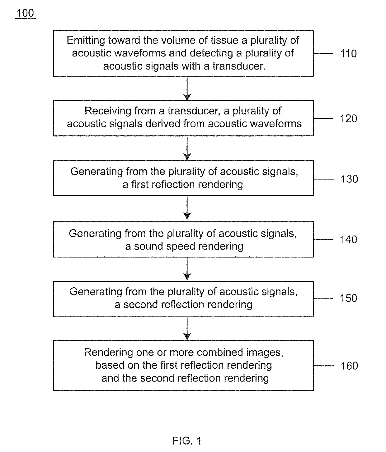
[0173]Clinical studies were conducted to develop a method of generating an enhanced image of a volume of tissue and a method for characterizing a volume of breast tissue of a patient. Results are presented from clinical studies that utilize breast imaging that is based on ultrasound tomography, which quantifies tissue characteristics while also producing 3-D images of breast anatomy, which methods described herein may include.

[0174]Informed consent was obtained from all patients, prospectively recruited in an IRB-approved protocol following HIPAA guidelines. Coronal images were produced by tomographic algorithms for reflection, sound speed and attenuation. All images were reviewed by a board-certified radiologist with more than 20 years of experience in breast imaging and US-technology development. In the first phase of the study, UST images were compared to multi-modal imaging to determine the appearance of lesions and breast parenchyma. In the second phase of the study, correlativ...


PUM


Abstract

The present invention provides improved methods and systems for generating enhanced images of a volume of tissue. In an aspect, the method comprises receiving from a transducer, a plurality of acoustic signals derived from acoustic waveforms transmitted through the volume of tissue; generating from the acoustic signals, a first reflection rendering that characterizes sound reflection, the first reflection rendering comprising a first distribution of reflection values across a region of the volume of tissue; generating from the acoustic signals, a sound speed rendering that characterizes sound speed, the sound speed rendering comprising a distribution of sound speed values across the region; generating from the sound speed rendering, a second reflection rendering that characterizes sound reflection, the second reflection rendering comprising a second distribution of reflection values across the region; and rendering one or more combined images, based on the first reflection rendering and the second reflection rendering.

Description

CROSS-REFERENCE[0001]This application claims the benefit of provisional patent application U.S. Prov. Ser. App. No. 62 / 429,542 , filed Dec. 2, 2016, entitled “Waveform Enhanced Reflection for Ultrasound Tomography”, and U.S. Prov. Ser. App. No. 62 / 429,563 , filed Dec. 2, 2016, entitled “Margin Boundary Characterization and Region of Interest Diagnostics for Ultrasound Tomography”, which are each incorporated herein by reference in their entirety.[0002]The subject matter of this application is related to the following patent applications: U.S. patent application Ser. No. 14 / 817,470 entitled “Method for Generating an Enhanced Image of A Volume of Tissue”; U.S. patent application Ser. No. 14 / 819,091 entitled “Ultrasound Waveform Tomography Method and System”; and P.C.T. International App. Pub. No. WO2017040866 entitled “Tissue Imaging and Analysis Using Ultrasound Waveform Tomography”, which are each incorporated herein by reference in their entirety.STATEMENT AS TO FEDERALLY SPONSORED...

Claims


Application Information

Patent Timeline
Patent Type & Authority Patents(United States)
IPC IPC(8): A61B8/13A61B8/00G06T5/00A61B8/15A61B8/08
CPCA61B8/0825A61B8/085A61B8/13A61B8/15A61B8/5207A61B8/5253G06T5/008A61B8/406G06T2207/10136
Inventor DURIC, NEBOJSALITTRUP, PETER J.SANDHU, GURSHARAN SINGHKRYCIA, MARKSAK, MARK
Owner DELPHINUS MEDICAL TECH
Why Eureka
Try Eureka