Systems and methods for inferring fuel vapor canister loading rate

a technology of fuel vapor canisters and loading rates, which is applied in the direction of machines/engines, combustion air/fuel air treatment, electric control, etc., can solve the problems of limiting limiting the total fuel vapor stored within the fuel vapor canister for a given refueling event, and going undiagnosed, so as to limit the rate of fuel vapor canister loading

Active Publication Date: 2019-07-30
FORD GLOBAL TECH LLC
View PDF11 Cites 3 Cited by
  • Summary
  • Abstract
  • Description
  • Claims
  • Application Information

AI Technical Summary

Benefits of technology

[0006]The fuel tank may be further coupled to a vapor recovery line (vapor recirculation line) which may also be coupled to the fuel vapor canister and the fuel filler neck. The vapor recovery line may be configured to circulate and / or hold a percentage of refueling vapors, thus limiting the rate of fuel vapor canister loading. Further, depending on the fuel dispenser, the fuel vapors within the vapor recovery line may be returned to the fuel dispenser, thus limiting the total fuel vapor stored within the fuel vapor canister for a given refueling event.
[0009]Thus, the inventors herein have recognized the above issues, and have developed systems and methods to at least partially address them. In one example, a method is provided, comprising testing for undesired evaporative emissions from a fuel system and / or an evaporative emissions system in a first mode when a vapor recovery line, configured to circulate and / or hold a percentage of refueling vapors, is degraded as determined by a steady-state pressure in the vapor recovery line during a refueling event, and testing for the undesired evaporative emissions in a second mode when the vapor recovery line is not degraded. In one example, testing for undesired evaporative emissions from the fuel system and / or the evaporative emissions system in the first mode includes conducting the test responsive to a fuel level in a fuel tank of the vehicle below a threshold fuel level, and wherein testing for undesired evaporative emissions from the fuel system and / or the evaporative emissions system in the second mode includes conducting the test responsive to the fuel level in the fuel tank being either greater than, or less than, the threshold fuel level. For example, when the fuel level is greater than the threshold fuel level and the vapor recovery line is degraded, a portion of the fuel system is isolated from another portion of the fuel system. In one example, the portion of the fuel system that is isolated includes a fuel filler system of the fuel system. In this way, an entirety of the fuel system and evaporative emissions system may be tested for the presence or absence of undesired evaporative emissions, even under conditions where the vapor recovery line is degraded. By conducting a test for undesired evaporative emissions in the first mode when the recovery line is degraded, and conducting the test for undesired evaporative emissions in the second mode when the recovery line is not indicated to be degraded, undesired evaporative emissions may be reduced or avoided.

Problems solved by technology

The vapor recovery line may be configured to circulate and / or hold a percentage of refueling vapors, thus limiting the rate of fuel vapor canister loading.
Further, depending on the fuel dispenser, the fuel vapors within the vapor recovery line may be returned to the fuel dispenser, thus limiting the total fuel vapor stored within the fuel vapor canister for a given refueling event.
Unlike other blockages in the emissions control system, a blockage in the vapor recovery line may not necessarily result in pre-mature shutoff of the fuel dispenser, and may thus go undiagnosed.
This may lead to an underestimation of canister load following refueling, which may in turn lead to an increase in bleed emissions if canister purge operations are not updated to accurately reflect the current canister load.
While the fuel tank pressure during the refueling event can also be used to estimate the canister loading rate, the fuel tank pressure may not increase in accordance with a vapor recovery line blockage, and may thus not provide an accurate reflection of canister loading in the case of degradation.
Furthermore, in a case where the vapor recovery line is blocked or restricted, some areas of the fuel system and evaporative emissions system may become isolated from vacuum or positive pressure that is utilized to assess a presence or absence of undesired evaporative emissions stemming from the fuel system and evaporative emissions system.
If parts of the fuel system (e.g. fuel filler system) go undiagnosed, undesired evaporative emissions may increase.

Method used


Image

  • Systems and methods for inferring fuel vapor canister loading rate
  • Systems and methods for inferring fuel vapor canister loading rate
  • Systems and methods for inferring fuel vapor canister loading rate

Examples


Embodiment Construction

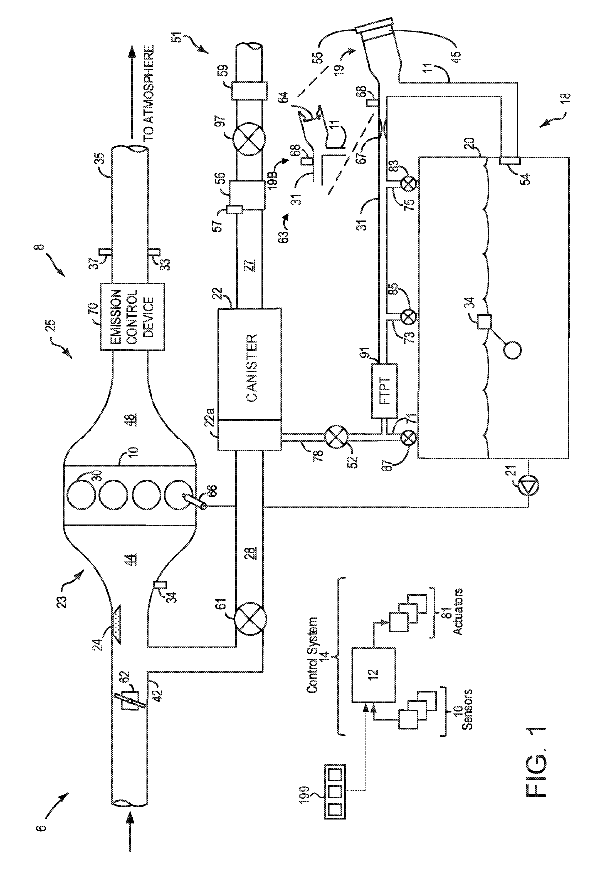
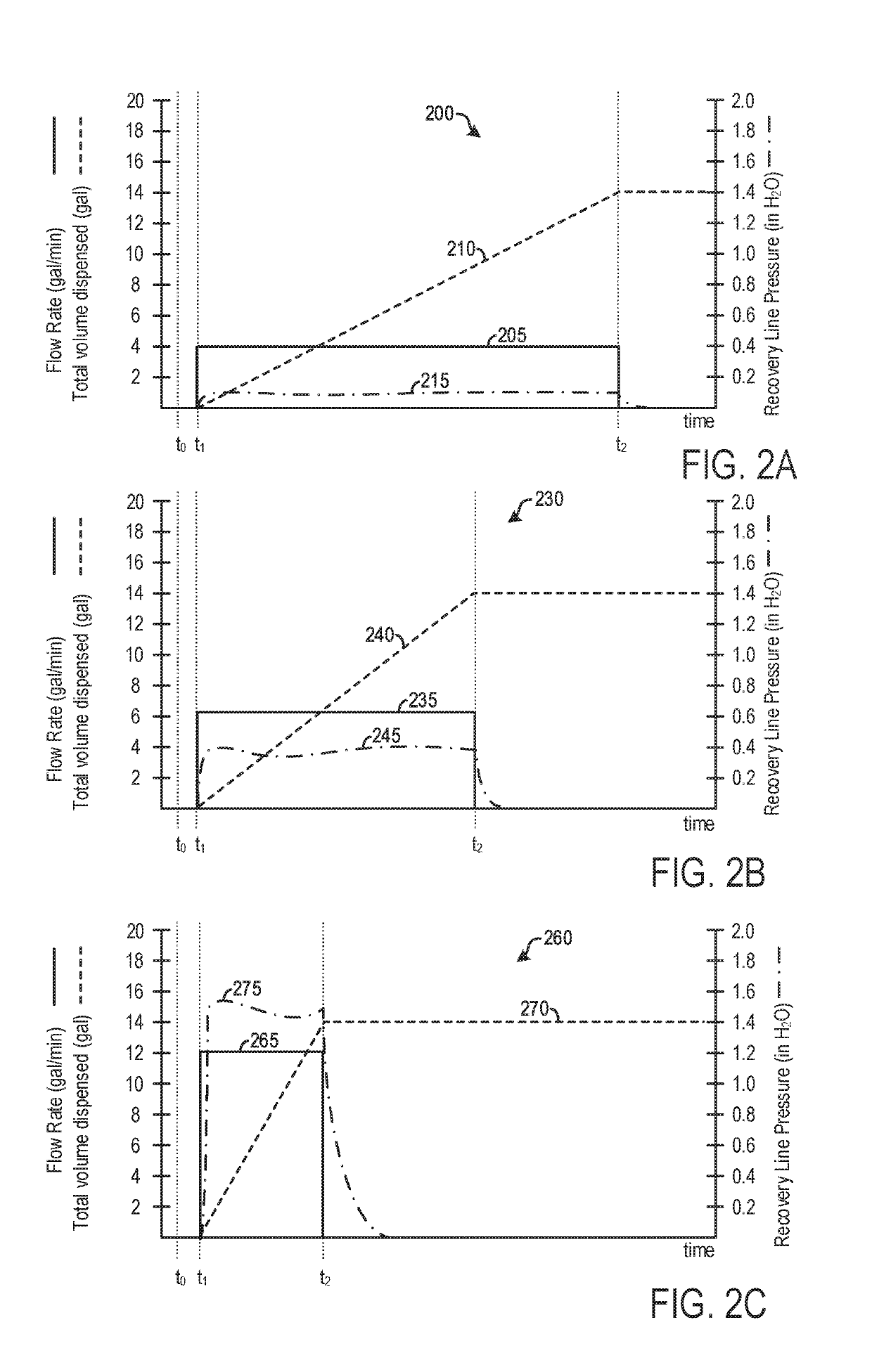
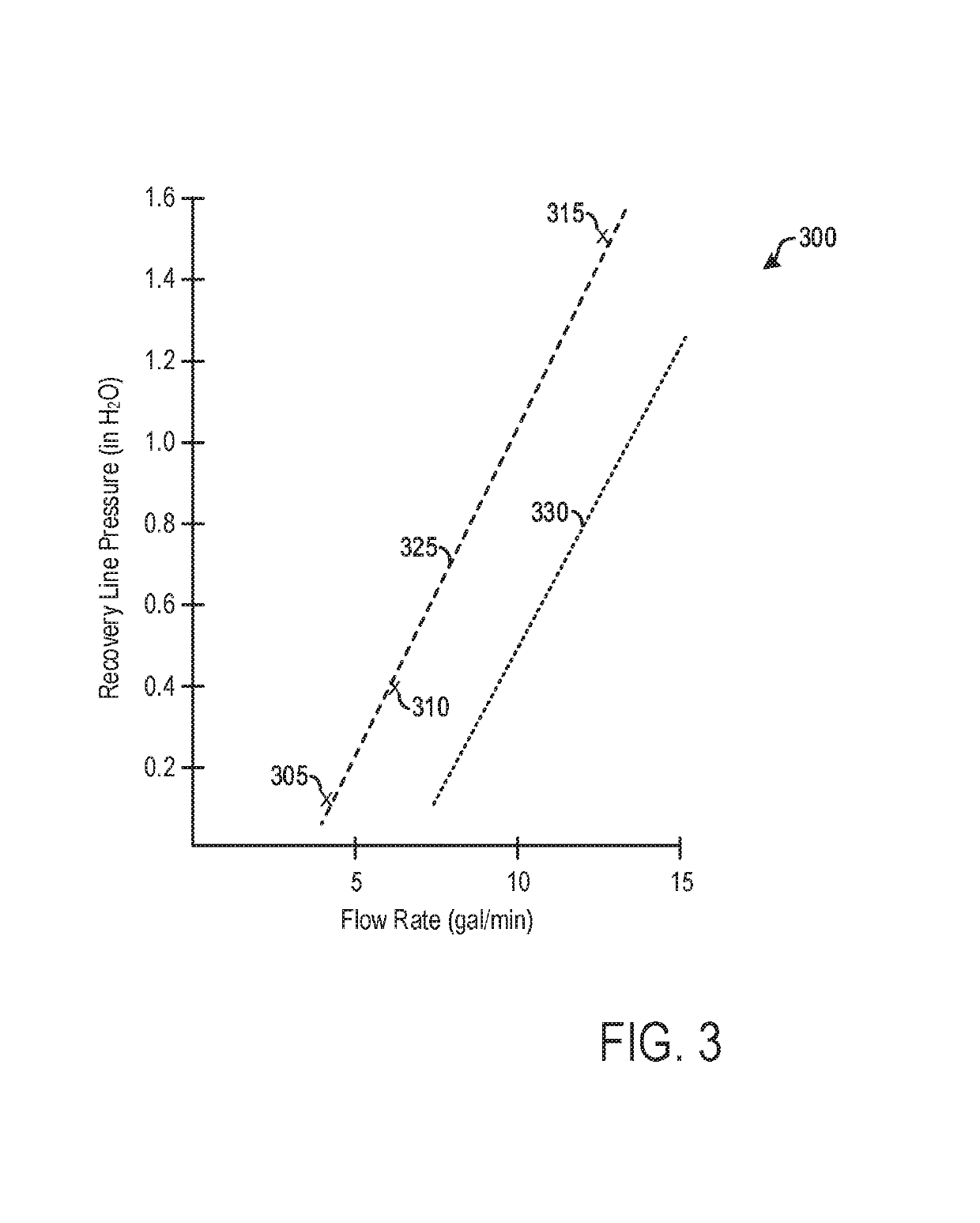
[0023]This detailed description relates to systems and methods for inferring a fuel vapor canister load. In particular, the fuel vapor canister load may be inferred based on the steady-state pressure in a vapor recovery line during a refueling event. The fuel vapor canister may be included in a hybrid vehicle, such as a plug-in electric hybrid vehicle, as depicted in FIG. 1. During a refueling event, the steady-state pressure in the vapor recovery line increases proportionately with the fuel dispensing rate, as shown in FIGS. 2A, 2B, 2C, and 3. However, if a blockage exists within the vapor recovery line, the vapor recovery line pressure may be less than expected based on the fuel dispensing rate, as shown in FIG. 3. This relationship may be exploited to determine vapor recovery line degradation, as well as a fuel canister load rate during a refueling event. FIG. 4 shows an example method for determining fuel canister load rate during a refueling event. FIG. 5 shows an example timel...


PUM


Abstract

Methods and systems are provided for indicating a restriction in a fuel system vapor recovery line. Responsive to such an indication, methods and systems are provided for taking mitigating actions such that an entirety of a vehicle fuel system and evaporative emissions system, including a fuel filler system, may be diagnosed as to a presence or absence of undesired evaporative emissions, even with the restriction in the vapor recovery line present. In this way, undesired evaporative emissions may be reduced or avoided, completion rates for such tests may be increased, and customer satisfaction may be improved.

Description

CROSS REFERENCE TO RELATED APPLICATIONS[0001]The present application is a continuation-in-part of U.S. patent application Ser. No. 14 / 606,704, entitled “Systems and Methods for Inferring Fuel Vapor Canister Loading Rate,” filed on Jan. 27, 2015.[0002]The present application is a continuation-in-part U.S. patent application Ser. No. 14 / 726,033, entitled “Systems and Methods for Inferring Fuel Vapor Canister Loading Rate,” which is a continuation-in-part of U.S. patent application Ser. No. 14 / 606,704, filed on May 29, 2015.[0003]The present application is a continuation-in-part U.S. patent application Ser. No. 14 / 868,101, entitled “Systems and Methods for Inferring Fuel Vapor Canister Loading Rate,” which is a continuation-in-part of U.S. patent application Ser. No. 14 / 606,704 filed on Sep. 28, 2015.[0004]The entire contents of each of the above-referenced applications are hereby incorporated by reference in their entirety for all purposes.BACKGROUND AND SUMMARY[0005]Vehicle emission ...

Claims


Application Information

Patent Timeline
Patent Type & Authority Patents(United States)
IPC IPC(8): F02D41/00B60K15/035F02M35/10F02D41/22F02M25/08B60K15/04
CPCF02D41/0032B60K15/03519F02D41/0045F02D41/22F02M25/0836F02M35/10019F02M25/0809F02D2041/225B60K2015/03514B60K2015/0419
Inventor DUDAR, AED M.PEARCE, RUSSELL RANDALLYANG, DENNIS SEUNG-MAN
Owner FORD GLOBAL TECH LLC
Why Eureka
Try Eureka