
Vehicle front structure

a front structure and vehicle technology, applied in the field of vehicle front structure, can solve problems such as inefficient distribution of load, and achieve the effect of relieving stress concentration

Inactive Publication Date: 2019-07-23
TOYOTA JIDOSHA KK
View PDF10 Cites 0 Cited by
  • Summary
  • Abstract
  • Description
  • Claims
  • Application Information

AI Technical Summary

Benefits of technology

[0006]The disclosure provides a vehicle front structure that has such a configuration that a first connection member and a second connection member are connected to a radiator support upper and that is able to relieve stress concentration on the first connection member in the event of a collision.
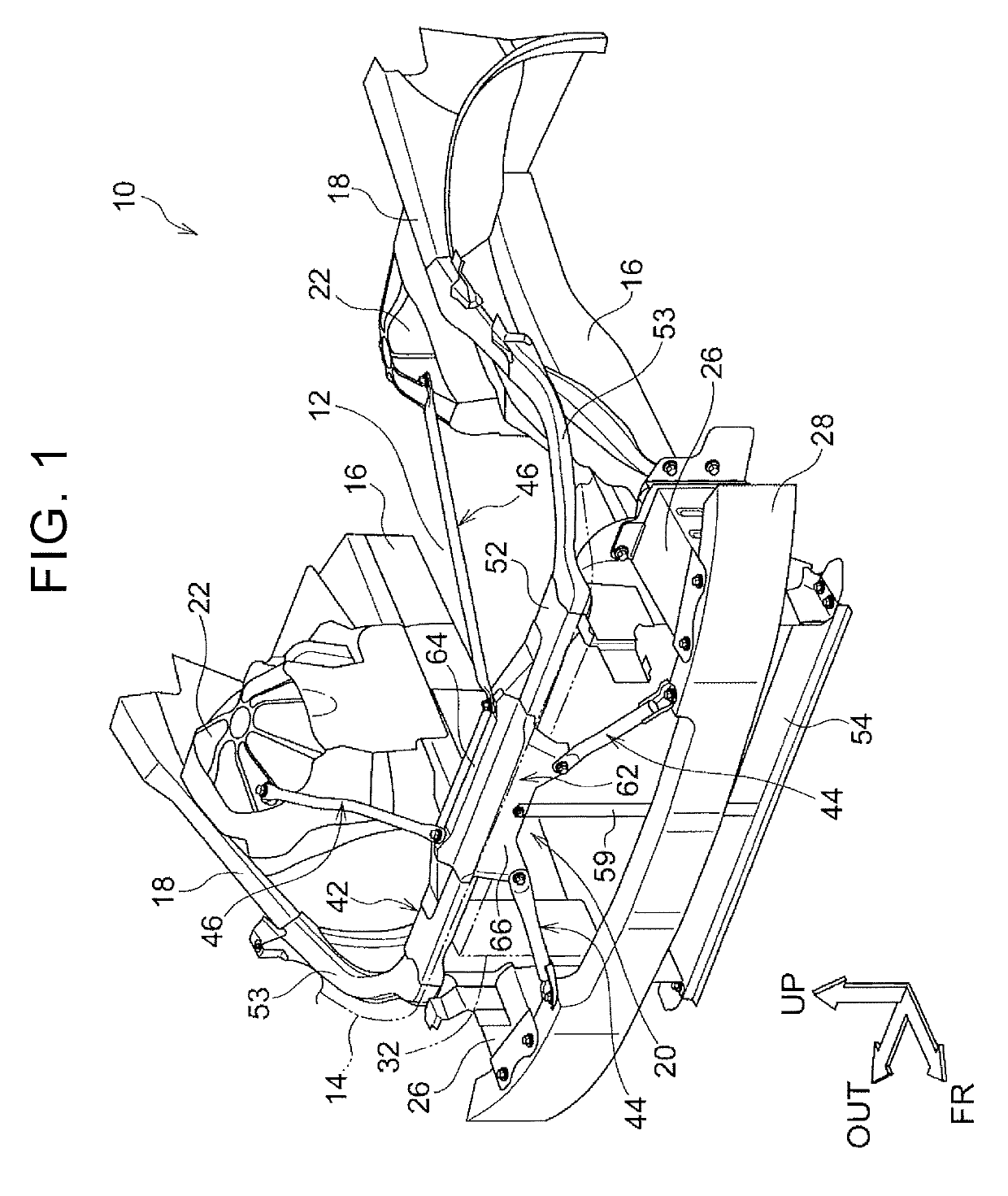
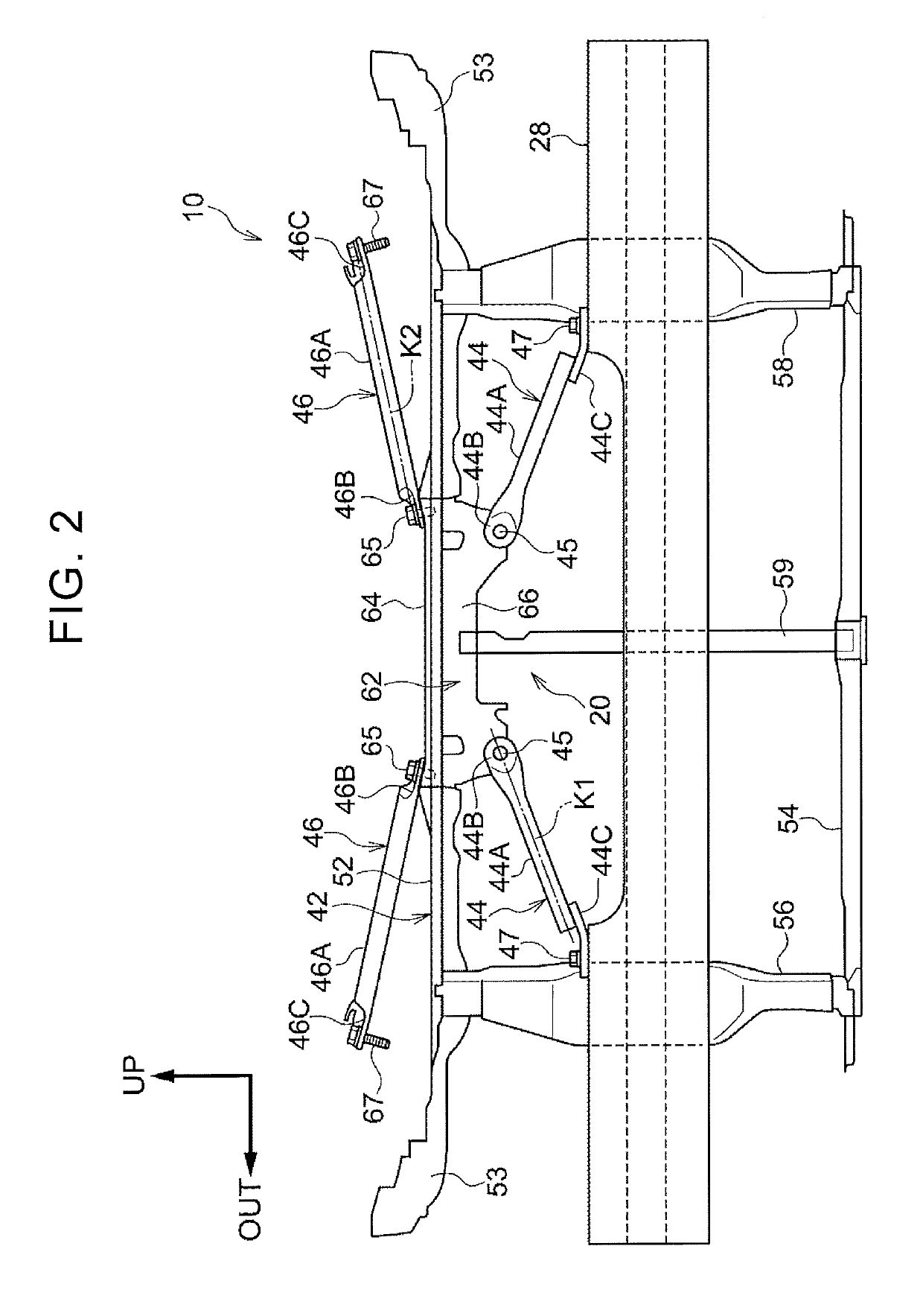
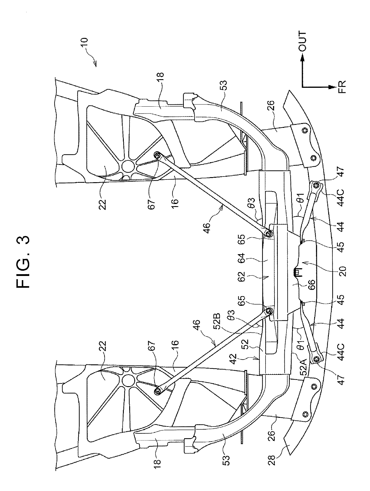
[0008]With the vehicle front structure according to the first aspect, a collision load input from the bumper reinforcement in the event of a collision of the vehicle is input to the radiator support upper via the first connection member. The collision load is further transferred from the radiator support upper via the second connection member to the vehicle component on a non-collision side. The portion of the second connection member, connected to the radiator support upper, is located on the central axis of the first connection member. For this reason, in comparison with the configuration in which the portion of the second connection member, connected to the radiator support upper, is located off from the central axis of the first connection member, a collision load input to the first connection member is easy to be input to the second connection member via the radiator support upper. Thus, in the configuration in which the first connection member and the second connection member are connected to the radiator support upper, it is possible to relieve stress concentration on the first connection member in the event of a collision.
[0010]With the above configuration, since the first connection member and the second connection member are substantially arranged on a straight line, a collision load input from the first connection member via the radiator support upper to the second connection member is easy to be transferred to the non-collision side of the second connection member in the central axis direction. Thus, it is possible to further relieve stress concentration on the first connection member in the event of a collision.
[0014]With the above configuration, the lock portion for locking the hood of the vehicle is integrally provided with the radiator support upper. The second connection member is connected to the radiator support upper via the lock portion. Thus, in comparison with the configuration in which the second connection member is connected to the radiator support upper and the lock portion is provided at a portion separated from the radiator support upper, space required to install the lock portion is reduced. That is, it is possible to ensure space for the lock portion without increasing the size of the vehicle.
[0016]With the vehicle front structure according to the second aspect, a collision load input from the bumper reinforcement in the event of a collision of the vehicle is input to the radiator support upper via the first connection member. The collision load is transferred from the radiator support upper via the second connection member to the vehicle component on a non-collision side. On at least one side of both sides in the vehicle width direction, the first connection position and the second connection position are aligned in the vehicle vertical direction. For this reason, a collision load input from the first connection member to the radiator support upper at the one-side first connection position is easy to be input from the radiator support upper to the second connection member at the one-side second connection position. Thus, stress is difficult to concentrate on the first connection member, so it is possible to relieve stress concentration on the first connection member in the event of a collision in the configuration in which the first connection member and the second connection member are connected to the radiator support upper.
[0018]With the vehicle front structure according to the third aspect, a collision load input from the side member in the event of a collision of the vehicle is input to the radiator support upper via the first connection member. The collision load is transferred from the radiator support upper via the second connection member to the vehicle component on a non-collision side. The portion of the second connection member, connected to the radiator support upper, is located on the central axis of the first connection member. For this reason, in comparison with the configuration in which the portion of the second connection member, connected to the radiator support upper, is located off from the central axis of the first connection member, a collision load input to the first connection member is easy to be input to the second connection member via the radiator support upper. Thus, stress is difficult to concentrate on the first connection member, so it is possible to relieve stress concentration on the first connection member in the event of a collision in the configuration in which the first connection member and the second connection member are connected to the radiator support upper.

Problems solved by technology

However, if the first connection member and the second connection member are merely connected to the radiator support upper, a collision load is not efficiently distributed from the first connection member to the second connection member and, as a result, stress (bending stress) may concentrate on the first connection member, so there is room for improvement.

Method used


Image

  • Vehicle front structure
  • Vehicle front structure
  • Vehicle front structure

Examples


first embodiment

[0030]Hereinafter, a vehicle 10 and a vehicle front structure 20 according to a first embodiment will be described with reference to FIG. 1 to FIG. 5A. In each drawing, the arrow FR indicates a vehicle front side, the arrow OUT indicates an outer side in a vehicle width direction, and the arrow UP indicates a vehicle upper side. Hereinafter, when an upper side and a lower side are simply described, the upper side and the lower side respectively indicate an upper side and a lower side in a vehicle vertical direction. When a right side and a left side are simply described, the right side and the left side respectively indicate a right side and a left side in the vehicle width direction in a situation in which the vehicle 10 is viewed from the front. A vehicle longitudinal direction, the vehicle width direction and the vehicle vertical direction are orthogonal to one another.

[0031]As shown in FIG. 1, the vehicle 10 includes the vehicle front structure 20 according to the first embodime...

second embodiment

[0067]Next, a vehicle front structure 70 according to a second embodiment will be described.

[0068]FIG. 6 schematically shows the vehicle front structure 70. The vehicle front structure 70 is provided in the vehicle 10 (see FIG. 1) according to the first embodiment instead of the vehicle front structure 20 (see FIG. 1). Like reference numerals denote members and portions in the vehicle front structure 70, basically the same as the members and portions of the above-described first embodiment, and the description thereof is omitted.

[0069]The vehicle front structure 70 includes the radiator support upper 52, the two first braces 44, the two second braces 46, the center brace 59 and the center bracket 62. The vehicle front structure 70 differs from the vehicle front structure 20 only in the radiator support upper 52-side connected position of each second brace 46. In the vehicle front structure 70, the first brace 44 are respectively provided on both sides in the vehicle width direction,...

third embodiment

[0076]Next, a vehicle front structure 90 according to a third embodiment will be described.

[0077]FIG. 7 shows the vehicle front structure 90 provided in a vehicle 80 according to the third embodiment. The vehicle 80 includes a pair of right and left front side members 82 as an example of side members. Each front side member 82 extends in the vehicle longitudinal direction, and is coupled to a bumper reinforcement (not shown). The side member in the present embodiment includes not only a side member alone but also a side member including a crash box. The vehicle front structure 90 includes a radiator support upper 102, two first braces 94 and two second braces 96. The radiator support upper 102 constitutes part of a radiator support 92. Each first brace 94 serves as an example of a first connection member. Each second brace 96 serves as an example of a second connection member.

[0078]The radiator support 92 includes the radiator support upper 102, a radiator support lower 104, and rad...


PUM


Abstract

A vehicle front structure includes a radiator support upper, a first connection member and a second connection member. The radiator support upper is provided with a connected portion on an inner side with respect to both ends of the radiator support upper in a vehicle width direction. When viewed in a vehicle longitudinal direction, the first connection member connects the connected portion with a bumper reinforcement in an oblique direction such that a portion of the first connection member, connected to the connected portion, is located on an inner side in the vehicle width direction with respect to a portion of the first connection member, connected to the bumper reinforcement. The second connection member connects the radiator support upper with a vehicle component. A portion of the second connection member, connected to the radiator support upper, is located on a central axis of the first connection member.

Description

INCORPORATION BY REFERENCE[0001]The disclosure of Japanese Patent Application No. 2016-249697 filed on Dec. 22, 2016 including the specification, drawings and abstract is incorporated herein by reference in its entirety.BACKGROUND1. Technical Field[0002]The disclosure relates to a vehicle front structure.2. Description of Related Art[0003]Japanese Patent Application Publication No. 2009-67184 (JP 2009-067184 A) describes a vehicle body front structure. The vehicle body front structure includes a pair of bulkhead front stays. The bulkhead front stays suspend an upper side center of a bulkhead connection body and bumper extension members. The bulkhead connection body is connected to front side frames. The bumper extension members are connected to a front bumper beam.SUMMARY[0004]There is a vehicle front structure in which a first connection member and a second connection member are connected to a radiator support upper that constitutes part of a radiator support that supports a radiat...

Claims


Application Information

Patent Timeline
Patent Type & Authority Patents(United States)
IPC IPC(8): B62D25/08B60K11/04B62D21/15B60R19/34
CPCB62D25/084B60K11/04B62D21/152B60Y2306/01B60R19/34B62D25/08
Inventor HAYASHI, TAKANORISATO, KENJIYAMATANI, MAMIKO
Owner TOYOTA JIDOSHA KK
Learn More