
Air massage device for pedicure spa and method

a pedicure spa and air massage technology, applied in bathing devices, chiropractic devices, physical therapy, etc., can solve the problems of motor burnout, inability to effectively detect fluids or water in spa devices and settings, foot spas,

Active Publication Date: 2019-07-23
LURACO INC
View PDF8 Cites 5 Cited by
  • Summary
  • Abstract
  • Description
  • Claims
  • Application Information

AI Technical Summary

Benefits of technology

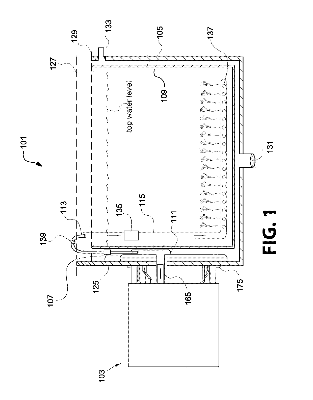
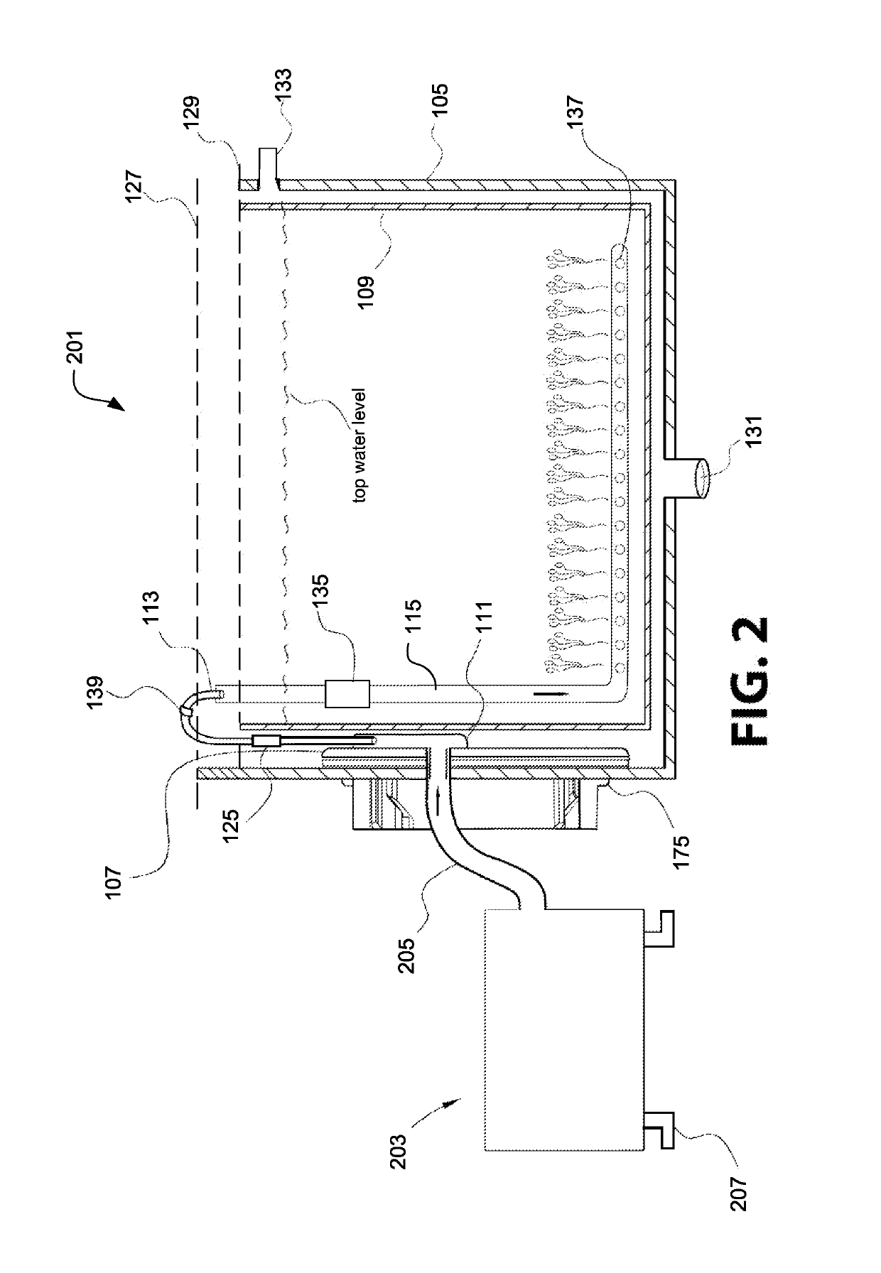
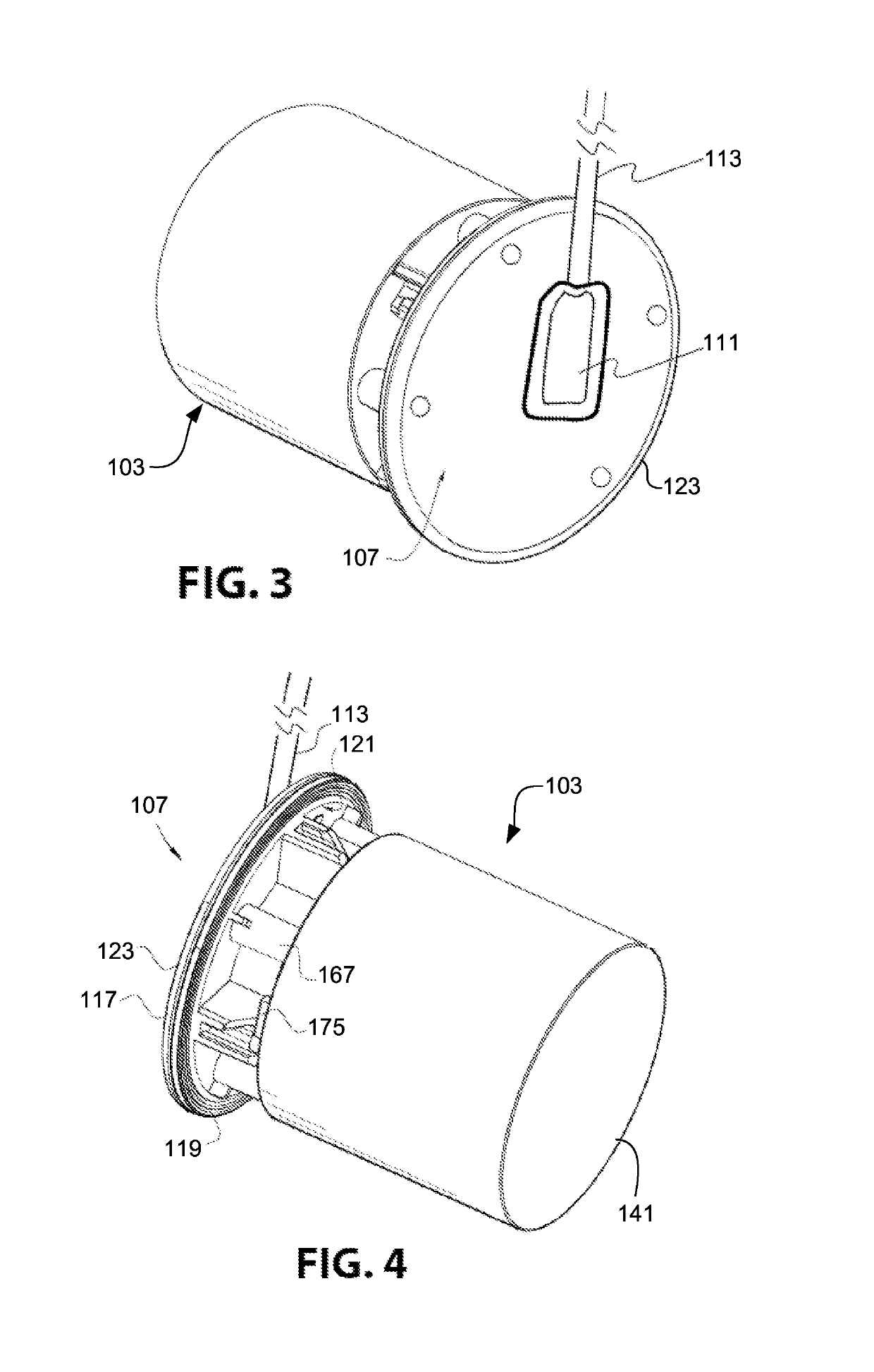
The present invention is a system for dispensing air to a pedicure spa basin in the manicure and pedicure industries. The system includes an air pump mounted on a sidewall of the basin and a disposable air dispenser to distribute air to the basin. The air pump creates air flow and the mounting housing with an air nozzle dispenses air into the basin. The system also includes a disposable air dispenser for distributing air to the basin. The system can be used with a liner and a contactless fluid sensor assembly. The technical effects of the system include improved air circulation in the spa basin, increased efficiency of air pump, and improved hygiene and safety.

Problems solved by technology

But with a liner, traditional water sensors in spa devices and settings, such as foot spas, will not be able to effectively detect fluids or water anymore.
The seals will wear to the point where water will enter the motor and consequently, the entering water may cause the motor to burn out.
This is expensive and may take several hours in which to perform.
Further, because typical spa devices have extensive piping systems that are built into the spa device to transport air and water, the spa devices are traditionally difficult to clean.
This results in downtime and complicated maintenance schedules to clean such spa devices.
Furthermore, if a spa device has a light source associated with it, to replace or repair such a light source can be time consuming and complicated when the light source is not easily accessible.
Additionally, for magnetic coupling-type pumps, it is almost impossible to have a perfect alignment between the motor shaft axis and the impeller rotation axis.
The imperfect alignment or misalignment will result in high vibration noise.

Method used


Image

  • Air massage device for pedicure spa and method
  • Air massage device for pedicure spa and method
  • Air massage device for pedicure spa and method

Examples


Embodiment Construction

[0034]Illustrative embodiments of the preferred embodiment are described below. In the interest of clarity, not all features of an actual implementation are described in this specification. It will of course be appreciated that in the development of any such actual embodiment, numerous implementation-specific decisions must be made to achieve the developer's specific goals, such as compliance with system-related and business-related constraints, which will vary from one implementation to another. Moreover, it will be appreciated that such a development effort might be complex and time-consuming but would nevertheless be a routine undertaking for those of ordinary skill in the art having the benefit of this disclosure.

[0035]In the specification, reference may be made to the spatial relationships between various components and to the spatial orientation of various aspects of components as the devices are depicted in the attached drawings. However, as will be recognized by those skille...


PUM


Abstract

An air pump for dispensing air massage therapy to a basin is provided. It may be used and with a disposal liner. The air pump includes a motor, an air generator, a mounting housing member, a gasket or seal, and an air nozzle. The air pump assembly includes the air pump and the air dispenser. The air pump preferably also includes a printed circuit board (PCB), a PCB cover, an LED light, an infrared light, and a contactless fluid sensor. The present invention is also directed to a pump apparatus that includes an air pump as described, a power source, and / or a control apparatus.

Description

BACKGROUND1. Field of the Invention[0001]The present invention generally relates to spa devices, components, and systems. More specifically, the present invention is directed to an air pump assembly that is designed and configured to be mounted to the wall of a basin for providing air massage therapy to a user. It may be used with a disposable liner.2. Description of Related Art[0002]Spa devices, components, and systems are known in the art. Spa devices are used in commercial and recreational settings for hydrotherapy, massage, stimulation, pedicure, and bathing purposes. In the spa application setting, the issues with sanitization in the spa industry today require the use of a liner, such as a disposable liner. But with a liner, traditional water sensors in spa devices and settings, such as foot spas, will not be able to effectively detect fluids or water anymore. Thus, there exists a need for a pump having a contactless, fluid sensor adapted for use with a liner for dispensing a f...

Claims


Application Information

Patent Timeline
Patent Type & Authority Patents(United States)
IPC IPC(8): A61H33/00A61H33/02A61H35/00
CPCA61H33/6026A61H35/006A61H33/6047A61H33/6042A61H33/6063A61H2033/023A61H2033/0083A61H2201/5058A61H1/00A61H33/005A61H33/0095A61H33/02A61H33/026A61H33/028A61H33/6005A61H33/6068A61H2033/0054A61H2033/0058A61H2201/0111A61H2201/0188A61H2201/0221A61H2201/1207A61H2201/1688A61H2201/5023A61H2201/5097A61H2203/02A61H2205/12
Inventor LE, KEVINLE, THANH
Owner LURACO INC
Learn More