
Power amplifier for millimeter wave devices

a technology of power amplifier and millimeter wave, which is applied in the direction of rf amplifier, amplifier with semiconductor devices/discharge tubes, transmission, etc., can solve the problems of consuming a relatively large amount of power, affecting the operation of the power amplifier, and the use of the millimeter wave device. , to achieve the effect of reducing power consumption, reducing size and increasing operating frequency

Active Publication Date: 2019-07-16
GLOBALFOUNDRIES U S INC
View PDF9 Cites 21 Cited by
  • Summary
  • Abstract
  • Description
  • Claims
  • Application Information

AI Technical Summary

Benefits of technology

[0010]Embodiments herein may provide power amplifier circuits with one or more of reduced size, reduced power consumption, or increased operating frequency.

Problems solved by technology

Implementing mm-wave applications produces many challenges when designing circuits for these applications, special consideration is to be given to designing power amplifiers.
In light of the ongoing race to reduce device sizes and / or power consumptions, known power amplifiers have undesirably high power consumption and undesirably large size for use in contemporary devices.
These problems are particularly pronounced for millimeter wave devices, such as vehicular radar devices, 5G telecommunication devices, and the like.
However, providing multiple programmable current sources consumes a relatively large amount of power and leads to upconversion of noise provided by the multiple programmable current sources.
AC coupling reduces the power amplification of the circuit, thereby requiring greater input power to generate a desired output power level.

Method used


Image

  • Power amplifier for millimeter wave devices
  • Power amplifier for millimeter wave devices
  • Power amplifier for millimeter wave devices

Examples


Embodiment Construction

[0026]Various illustrative embodiments of the invention are described below. In the interest of clarity, not all features of an actual implementation are described in this specification. It will of course be appreciated that in the development of any such actual embodiment, numerous implementation-specific decisions must be made to achieve the developers' specific goals, such as compliance with system-related and business-related constraints, which will vary from one implementation to another. Moreover, it will be appreciated that such a development effort might be complex and time-consuming, but would nevertheless be a routine undertaking for those of ordinary skill in the art having the benefit of this disclosure.

[0027]The present subject matter will now be described with reference to the attached figures. Various structures, systems, and devices are schematically depicted in the drawings for purposes of explanation only and so as to not obscure the present disclosure with details...


PUM


Abstract

We disclose apparatus which may provide power amplification in millimeter-wave devices with reduced size and reduced power consumption, and methods of using such apparatus. One such apparatus comprises an input transformer; a first differential pair of injection transistors comprising a first transistor and a second transistor; a first back gate voltage source configured to provide a first back gate voltage to the first transistor; a second back gate voltage source configured to provide a second back gate voltage to the second transistor; a second differential pair of oscillator core transistors comprising a third transistor and a fourth transistor, wherein the third transistor and the fourth transistor are cross-coupled; a third back gate voltage source configured to provide a third back gate voltage to the third transistor; a fourth back gate voltage source configured to provide a fourth back gate voltage to the fourth transistor; and an output transformer.

Description

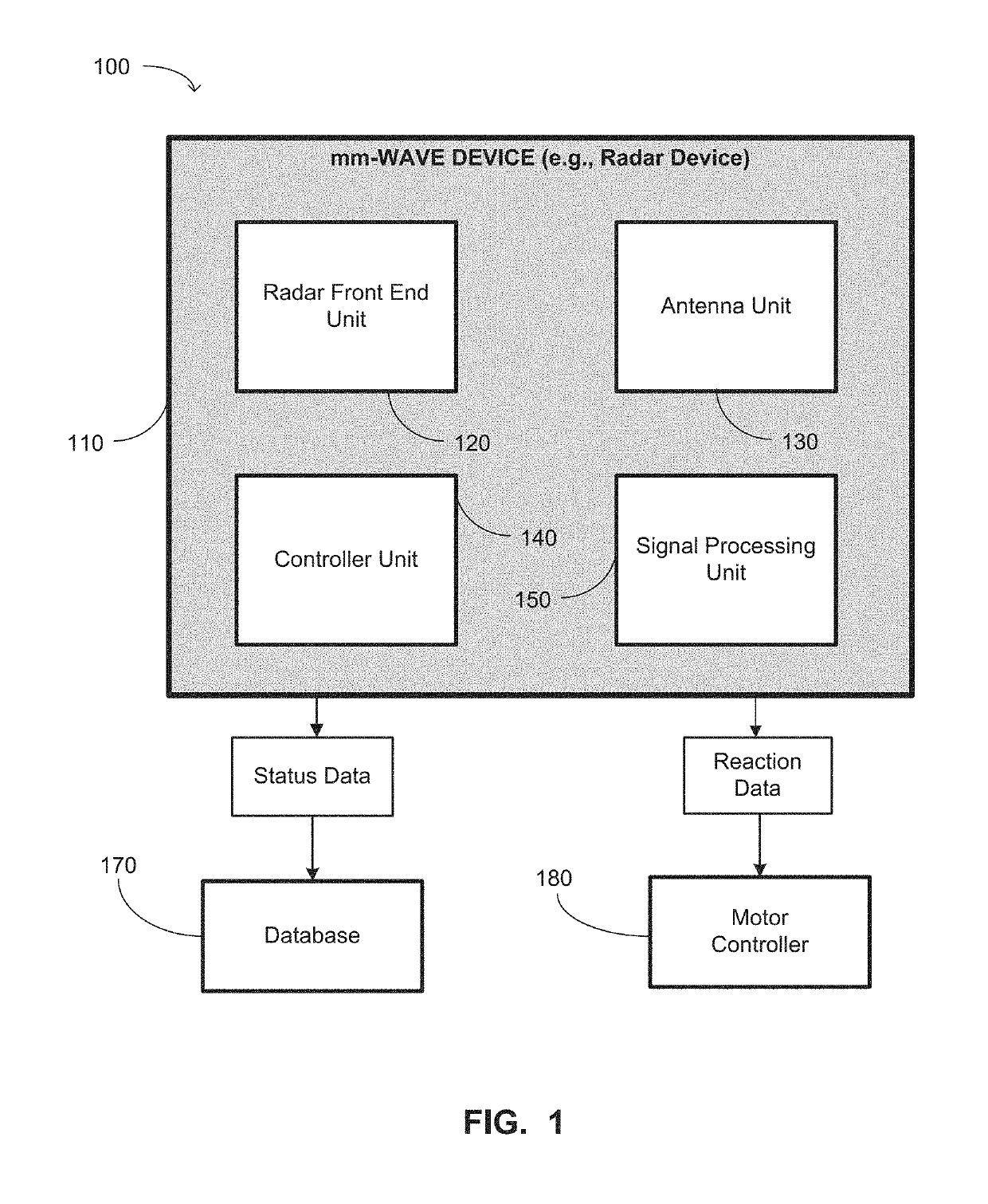
BACKGROUND OF THE INVENTIONField of the Invention[0001]Generally, the present disclosure relates to sophisticated semiconductor devices, and, more specifically, to power amplifiers for millimeter wave devices.Description of the Related Art[0002]There have been many advances in devices that use millimeter wave (mm-wave) signals. Semiconductor devices that involve mm-wave applications include devices that operate based on the electromagnetic spectrum of radio band frequencies in the range of about 30 Gigahertz (GHz) to about 300 GHz. The mm-wave radio waves have a wavelength in the range of 1 millimeter (mm) to about 10 mm, which corresponds to a radio frequency of 30 GHz to about 300 GHz. This band of frequencies is sometimes referred to as extremely high frequency (EHF) frequency band range. Examples of applications of mm-wave application include radar devices, high-speed communication devices (e.g., wireless gigabit (WiGig) devices,), etc. Radar devices have been implemented in var...

Claims


Application Information

Patent Timeline
Patent Type & Authority Patents(United States)
IPC IPC(8): H03F1/02H03F3/21H03F3/193H03F3/45H04B1/04
CPCH03F1/0205H03F3/193H03F3/21H03F3/45165H04B1/04H04B2001/0408H03F2200/451H03F2200/534H03F2200/541H03F3/45085H03F2203/45318H03F2203/45621H03F2203/45731
Inventor LEE, SEE TAURBELLAOUAR, ABDELLATIF
Owner GLOBALFOUNDRIES U S INC
Learn More