
Display system with static green primary color reduction filter

a technology of color reduction filter and display system, which is applied in the field of display system with static green primary color reduction filter, can solve the problems of loss of contrast ratio and bits, and loss of electronic correction image bit depth (grey scale), so as to reduce the operating temperature of the imaging chip, avoid or reduce the need for electronic correction, and light energy.

Active Publication Date: 2019-07-09
BARCO VISUAL (BEIJING) ELECTRONICS CO LTD
View PDF25 Cites 0 Cited by
  • Summary
  • Abstract
  • Description
  • Claims
  • Application Information

AI Technical Summary

Benefits of technology

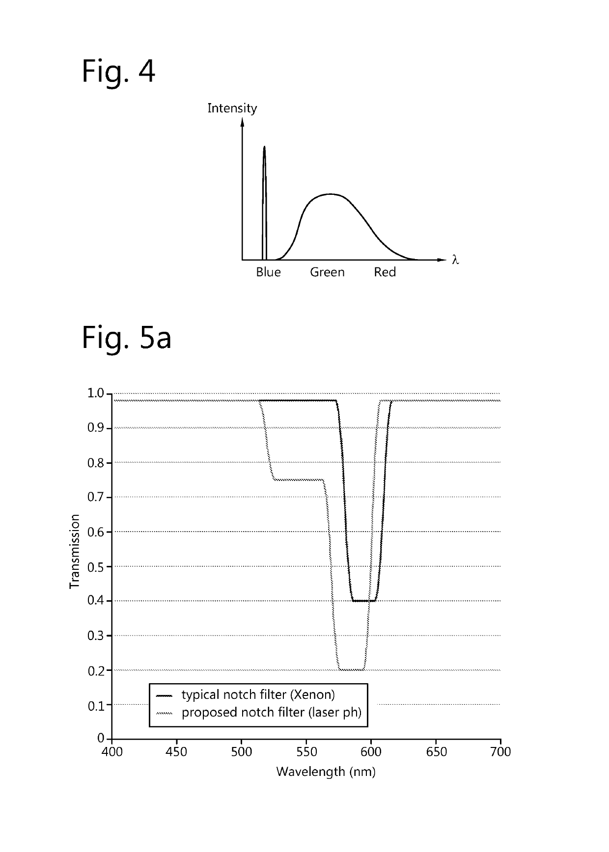
[0039]It is an advantage of the present invention to reduce the operating temperature of the imaging chip, by reducing the intensity of one of the wavebands before the imaging module, such as to avoid or reduce the need for electronic correction. In particular, the static green waveband reduction filter allows the removal of excess green light, which is thereby not provided to the green channel of the imaging module. So there is less light energy in the respective green color channel, whereby there is less cooling required. This reduction in cooling requirements results in a variety of advantages such as less noise, an increased lifetime, a higher reliability, etc.
[0040]Advantageously, the second blue beam is provided by splitting said first blue laser beam into said first and second blue laser beams.
[0041]Advantageously, the first and second blue laser beams are provided by means of at least one of a beam splitter, polarization diversity, wavelength diversity, spatial or angular diversity applied to said first blue laser beam.
[0042]Preferably, at least one or both of the first or second blue laser beams is provided with intensity reduction means.
[0044]Advantageously, said neutral density filters of different densities are arranged in a color filter wheel.

Problems solved by technology

One of the drawbacks of electronically corrected images is that the contrast ratio is lowered.
A second drawback of electronically corrected images is the loss in bit depth (grey scales).
A native white color point which is far from the target white point can lead to a significant loss of contrast ratio and of bits and thereby have a negative impact on image quality.
A third drawback of illuminating the light modulator with light that is not used on screen is the cooling needed to get rid of the absorbed amount of energy.
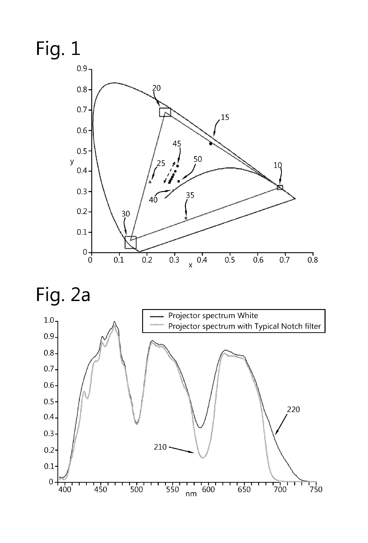
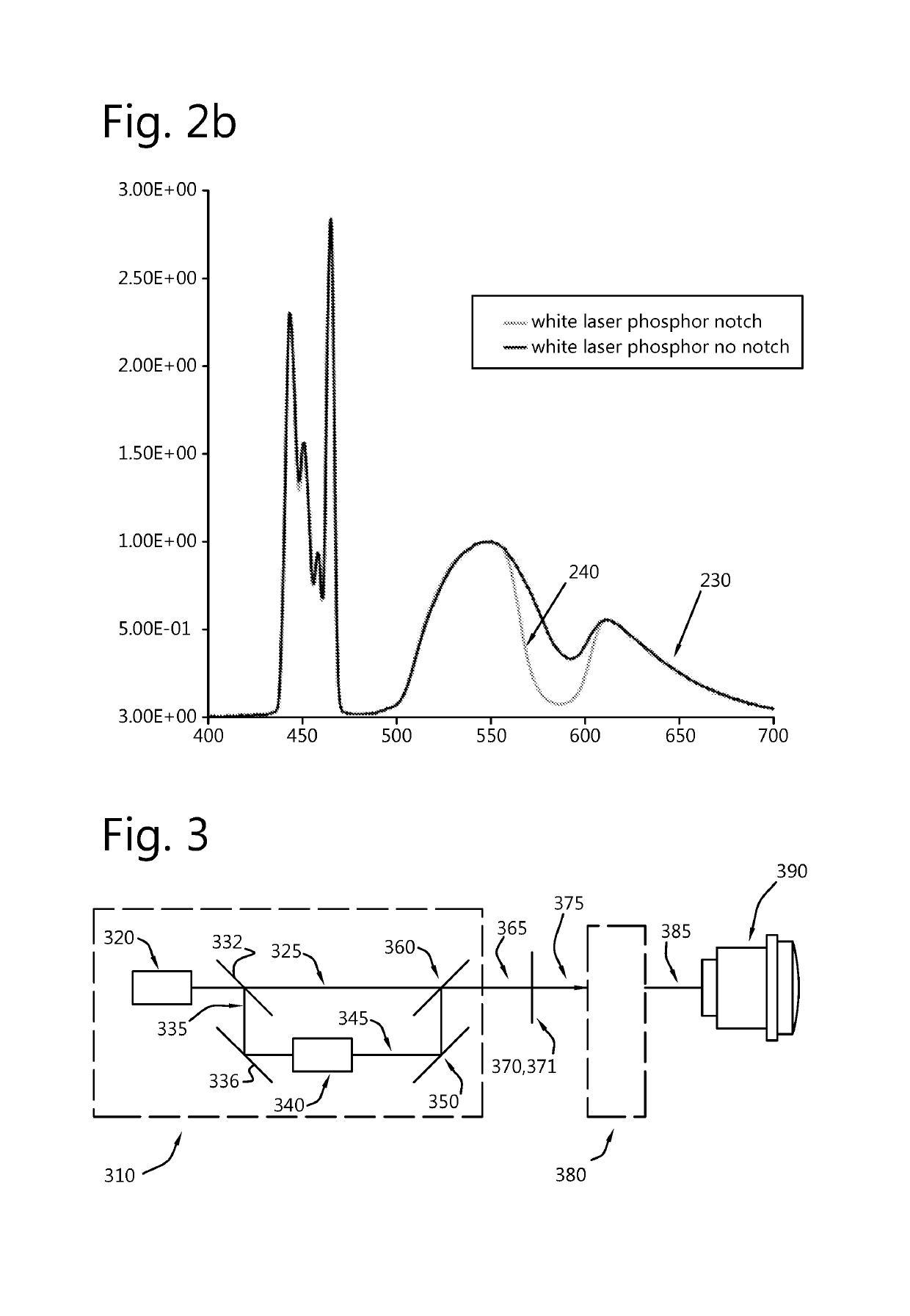
The main drawback of a laser phosphor light source with blue lasers and a phosphor is the lack of red light and the excess of green and yellow light in the spectrum of the projected image, as shown in spectrum 230 of FIG. 2b, which is the spectrum of the projected image after the color splitting and recombination taking place in an imaging module.
The result of this will be a loss of contrast ratio and bit depth or in general image quality and a higher then needed energy load on the light modulator, thereby generating additional heat in and around the light modulators.
Another problem typical for laser phosphor illuminated systems is the change of the white color point (white color shift) with dimming of the blue lasers for the phosphor excitation.

Method used


Image

  • Display system with static green primary color reduction filter
  • Display system with static green primary color reduction filter
  • Display system with static green primary color reduction filter

Examples


Embodiment Construction

[0082]The present invention will be described with respect to particular embodiments and with reference to certain drawings but the invention is not limited thereto but only by the claims. The drawings described are only schematic and are non-limiting. In the drawings, the size of some of the elements may be exaggerated and not drawn on scale for illustrative purposes. The dimensions and the relative dimensions do not correspond to actual reductions to practice of the invention.

[0083]Furthermore, the terms first, second and the like in the description and in the claims, are used for distinguishing between similar elements and not necessarily for describing a sequence, either temporally, spatially, in ranking or in any other manner. It is to be understood that the terms so used are interchangeable under appropriate circumstances and that the embodiments of the invention described herein are capable of operation in other sequences than described or illustrated herein.

[0084]Moreover, t...


PUM


Abstract

A projection system for generating an image with three primary colors, including a first and second blue laser beam, a wavelength conversion element for converting the second blue beam into a converted beam having a waveband including at least the second and third wavebands, a beam combiner for combining the first beam and the converted beam, which combination results in a white beam, a notch filter placed in the optical path of the white beam to form a modified white beam including at least the first, second and third wavebands provided to an imaging module, where a static waveband reduction filter is further provided for changing the wavelength of transmitted second waveband of the white beam, such as to adjust a projector white point shift.

Description

[0001]The present invention relates to improvements in projector systems, and to the provision of an optical assembly, a light projection system and a method of operating the system.BACKGROUND OF THE INVENTION[0002]Digital Cinema projectors have to project images according to the DCI (Digital Cinema Initiatives) standard. In this standard, the color gamut of the native (colors on screen without any electronic color correction) and the electronically color corrected gamut projected by a projection device is described.[0003]Colors can be defined with respect to standards, as the standards defined by DCI. In DCI standards, colors are defined with respect to CIE 1931 color spaces, quantitatively relating the colors as defined by their wavelengths to the physiological perception of colors in human vision. The CIE 1931 color space is shown in FIG. 1.[0004]FIG. 1 shows the requirements of a color gamut defined in the CIE 1931 color space to comply with DCI requirements. DCI standards requi...

Claims


Application Information

Patent Timeline
Patent Type & Authority Patents(United States)
IPC IPC(8): G03B21/14H04N9/00G02B5/20G03B21/20G02B27/14H04N9/31
CPCG02B27/149G02B5/20G03B21/204H04N9/3161H04N9/3111H04N9/3155H04N9/3158H04N9/00
Inventor COULIER, NICO GERARDWANG, XIAO YUNCHEDAD, ALLEL
Owner BARCO VISUAL (BEIJING) ELECTRONICS CO LTD
Learn More