
Systems and methods for monitoring and optimizing flare purge gas with a wireless rotameter

a technology of purge gas and wireless rotameter, which is applied in the direction of lighting and heating apparatus, combustion types, instruments, etc., can solve the problems of not optimizing the application of fuel gas, and achieve the effects of minimizing excess flaring and purging, adequate purging, and avoiding excessive flaring

Active Publication Date: 2019-07-09
SAUDI ARABIAN OIL CO
View PDF26 Cites 2 Cited by
  • Summary
  • Abstract
  • Description
  • Claims
  • Application Information

AI Technical Summary

Benefits of technology

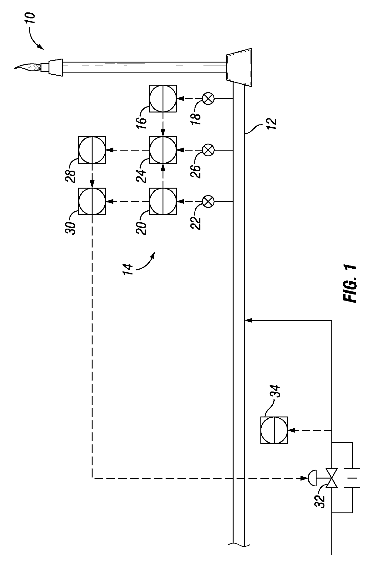
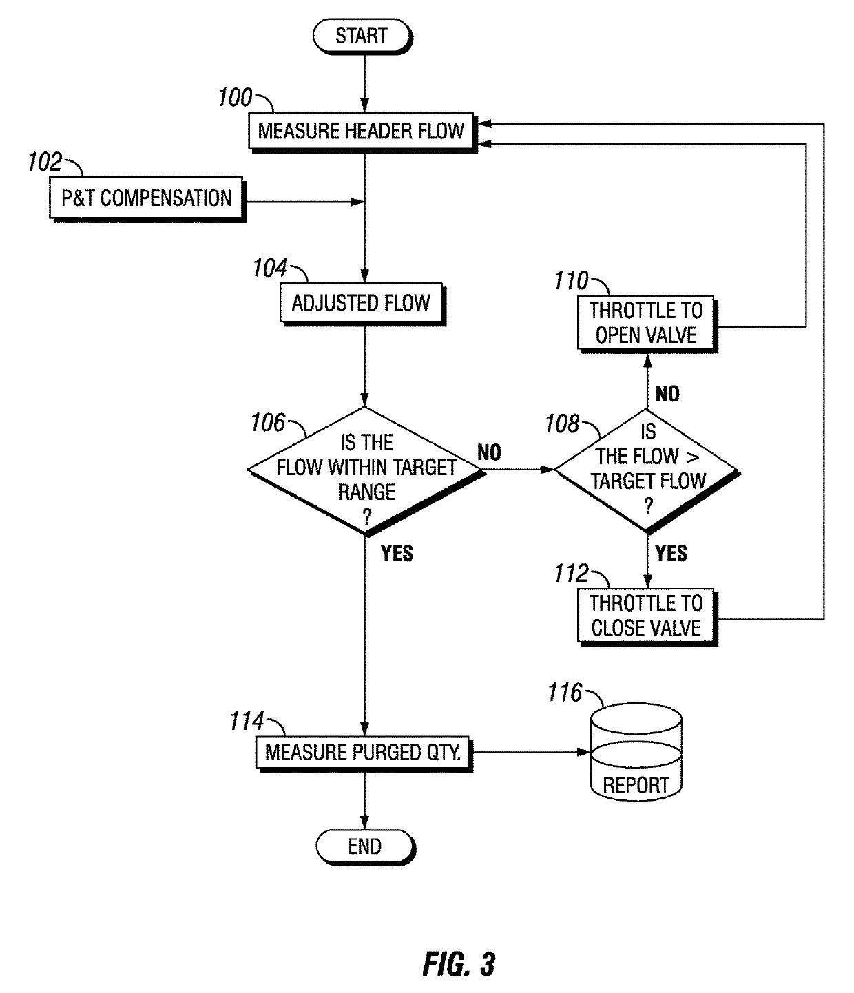
[0009]Embodiments disclosed herein provide system and methods for avoiding excessive flaring and ensuring adequate purging to the flare network system, by monitoring and controlling the fuel gas flow. In current systems, since the purge quantity is not monitored, the applied fuel gas is not optimized. Optimizing the flow of purge gas will minimize excess flaring and purging, limit greenhouse gas emission, and optimize energy and fuel consumption.

Problems solved by technology

In current systems, since the purge quantity is not monitored, the applied fuel gas is not optimized.

Method used


Image

  • Systems and methods for monitoring and optimizing flare purge gas with a wireless rotameter
  • Systems and methods for monitoring and optimizing flare purge gas with a wireless rotameter
  • Systems and methods for monitoring and optimizing flare purge gas with a wireless rotameter

Examples


Embodiment Construction

[0023]Embodiments of the present disclosure will now be described more fully hereinafter with reference to the accompanying drawings which illustrate embodiments of the disclosure. Systems and methods of this disclosure may, however, be embodied in many different forms and should not be construed as limited to the illustrated embodiments set forth herein. Rather, these embodiments are provided so that this disclosure will be thorough and complete, and will fully convey the scope of the disclosure to those skilled in the art. Like numbers refer to like elements throughout, and the prime notation, if used, indicates similar elements in alternative embodiments or positions.

[0024]In the following discussion, numerous specific details are set forth to provide a thorough understanding of the present disclosure. However, it will be obvious to those skilled in the art that embodiments of the present disclosure can be practiced without such specific details. Additionally, for the most part, ...


PUM


Abstract

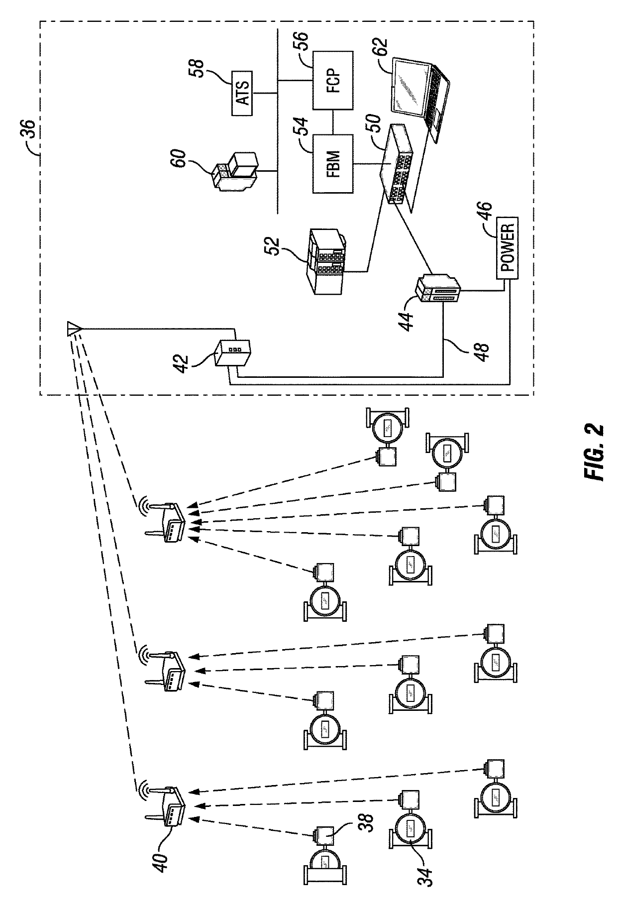
A method for optimizing purge gas of a flare system includes measuring a flow of flare fluids within a flare system to obtain a measured flow value. The flow of the flare fluids is compared to a target flow to obtain a difference between the flow of the flare fluids and the target flow. A control valve is operated to amend a flow of purge gas and the steps of measuring a flow of flare fluids and comparing the flow of the flare fluids to the target flow are repeated until the flow of the purge gas is within a target range. A value of the flow of purge gas is measured and transmitted wirelessly to a control system.

Description

BACKGROUND OF THE DISCLOSURE[0001]1. Field of the Disclosure[0002]The disclosure relates generally to flow meter monitoring and control assemblies and more specifically to the optimization of purge gas systems with a wireless rotameter.[0003]2. Description of the Related Art[0004]In oil refineries and in other oil and gas processing plants, relief devices that can emit hydrocarbons are connected to a flare or vent network. The flare or vent network ends up in a flare or vent stack which continuously emits the hydrocarbons to atmosphere. A vent stack does not burn the hydrocarbons and simply disposes them to the atmosphere at a safe location. Hence gas flow emitted by a vent stack is typically small. When the gas flows to be continuously disposed are quite high, the gas needs to be combusted before disposing it to the atmosphere. This consumption is achieved in a flare stack. The hydrocarbons are continuously combusted at the flare stack tip before disposing to atmosphere.[0005]If th...

Claims


Application Information

Patent Timeline
Patent Type & Authority Patents(United States)
IPC IPC(8): F23G7/08G01F1/22F23G5/50G01F1/24B08B9/032G01F15/00G01F15/04G01F15/06
CPCB08B9/0325F23G5/50F23G7/08F23G7/085G01F1/24G01F15/001G01F1/22G01F15/061G01F15/04
Inventor DANIEL, SELVAM
Owner SAUDI ARABIAN OIL CO
Learn More