Inkjet printing apparatus and control method
a technology of printing apparatus and control method, which is applied in the field ofinkjet printing apparatus, can solve the problems of difficult wiping of thickening ink generated by heat and evaporation, affecting the quality of printing,
- Summary
- Abstract
- Description
- Claims
- Application Information
AI Technical Summary
Benefits of technology
Problems solved by technology
Method used
Image

Examples
first exemplary embodiment
[0064]A first exemplary embodiment of the present invention is described below with reference to the above-described configuration. In the present exemplary embodiment, the purge operation is performed for each of the scanning operations. The schematic purge sequence (step S14) in the print sequence illustrated in FIG. 6 and the flowchart of the purge sequence are illustrated in FIGS. 8A and 8B.
[0065]If data for one scan is accumulated in the print buffer 121 after a print process begins, measurement of the number of ink ejections (D) from all of the nozzles during the print operation is started (step S23). Immediately after the measurement is started, the print operation for one scan is started (step S15). The number of ink ejections (D) can be measured using an ejection count measuring unit on the basis of, for example, print data stored in the print buffer 121 and font data stored in the font generation ROM 104. The ejection count measuring unit includes the MPU 102 that measures...
example 1
[0070]FIG. 9A illustrates an example of wiping traces (areas used for the purge operation) of the sheet member 31 after the sequence illustrated in FIGS. 8A and 8B is performed. In FIG. 9A, the winding direction is indicated by an arrow. Thus, the trace generated in the first purging operation is leftmost. Since the number of ink ejections (D) is greater than or equal to 5×10⁸ in first three scans and the eighth scan, the amount of winding is 7 mm, according to Table 1. In addition, since the number of ink ejections (D) is less than 1×10⁸ in each of the fourth to seventh scans and ninth scan, the amount of winding is 3 mm, according to Table 1.
second exemplary embodiment
[0074]Like the first exemplary embodiment, the purge operation is performed for each of the scans. According to the present exemplary embodiment, the sequence in the wiping operation (step S14) in the print sequence illustrated in FIG. 6 differs from that of the first exemplary embodiment. The schematic sequence in the wiping operation (step S14) and the flowchart of the sequence are illustrated in FIGS. 10A and 10B.
[0075]If data for one scan is accumulated in the print buffer 121 after the print process begins, measurement of the number of ink ejections (D1) is started (step S28). Immediately after the measurement is started, the print operation for one scan is started (step S15). After the one-scan operation is completed, part of the sheet member 31 used in the previous purge operation is collected through the winding operation illustrated in FIG. 7F (step S29). The amount of winding (X2) is selected from Table 1 in accordance with the number of ink ejections (D2) measured by the ...
PUM
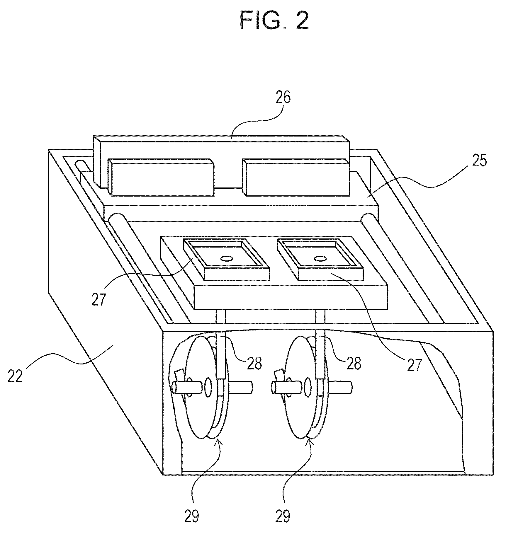
 Abstract
Description
Claims
Application Information
 - R&D
- Intellectual Property
- Life Sciences
- Materials
- Tech Scout
- Unparalleled Data Quality
- Higher Quality Content
- 60% Fewer Hallucinations
Browse by: Latest US Patents, China's latest patents, Technical Efficacy Thesaurus, Application Domain, Technology Topic, Popular Technical Reports.
© 2025 PatSnap. All rights reserved.Legal|Privacy policy|Modern Slavery Act Transparency Statement|Sitemap|About US| Contact US: help@patsnap.com