Apparatus for purging containers for storing sensitive materials

a technology for purging containers and sensitive materials, applied in electrical appliances, drying machines, light and heating equipment, etc., can solve the problems of contamination and deterioration of the contents stored in the container, and achieve the effect of modest power requirements for such control

Active Publication Date: 2015-12-15
ROYLAN DEV
View PDF53 Cites 5 Cited by
  • Summary
  • Abstract
  • Description
  • Claims
  • Application Information

AI Technical Summary

Benefits of technology

The patent text describes a way to design control units for purging containers using purge gas. By using the pressure from the purge gas supply and gas cylinders, the control units can be lightweight and portable with low power requirements. The time needed for purging can be adjusted based on the volume of the container, and the apparatus can be set up to trigger the purge at the desired time using sensors and associated circuitry. This saves power and avoids the need for power-hungry solenoid valves. The technical effect of the patent is to provide a more efficient and portable way to purge containers.

Problems solved by technology

After the sensitive materials, for example molecule compounds dissolved in DMSO, are placed in the enclosure, it is sealed and then purged using a purge gas and preferably left with the interior filled with inert gas at a pressure slightly above ambient so that if there is any problem with the sealing, the leakage occurs from the inside of the container to the outside rather than the other way round, which could lead to contamination and deterioration of the contents stored in the container.

Method used


Image

  • Apparatus for purging containers for storing sensitive materials
  • Apparatus for purging containers for storing sensitive materials
  • Apparatus for purging containers for storing sensitive materials

Examples


Embodiment Construction

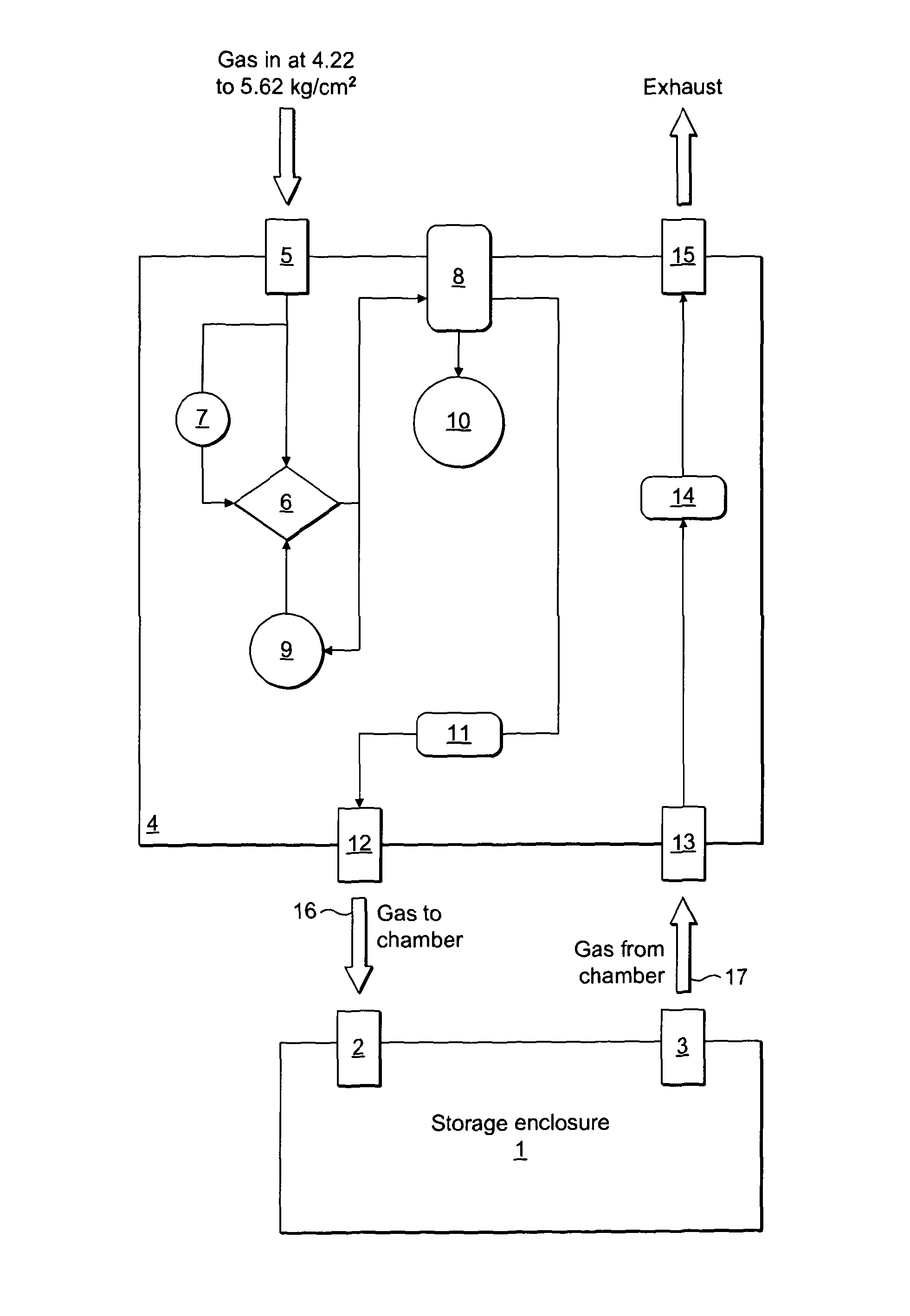
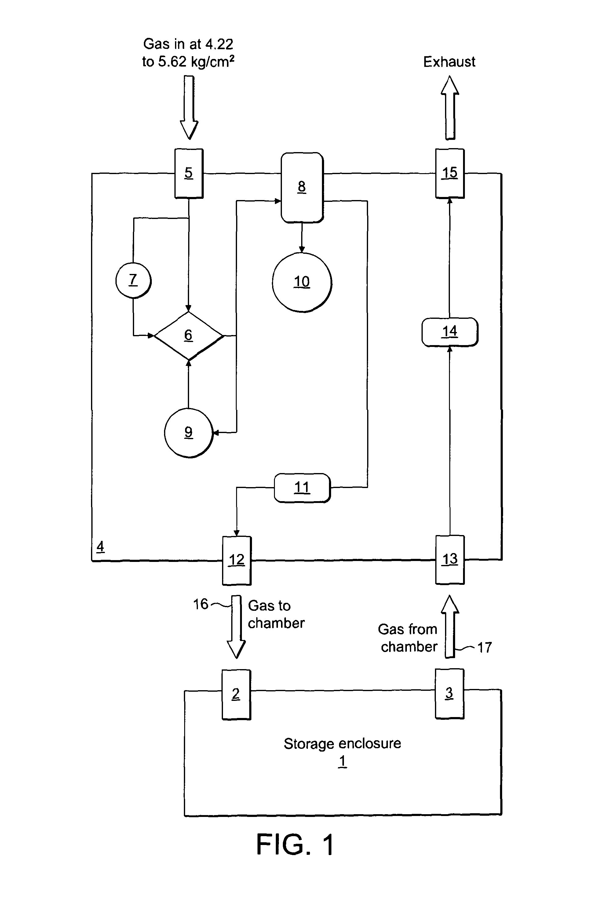
[0023]Referring to FIGS. 1 and 2 of the drawings, a purgeable rigid sealable storage container 1 of known design is provided with an inlet valve 2 and an exhaust valve 3, and is shown diagrammatically at the foot of FIG. 1. Valves 2 and 3 are both simple hose coupling valves which seal in the absence of excess pressure applied from the outside in the case of valve 2 and from the inside in the case of valve 3.

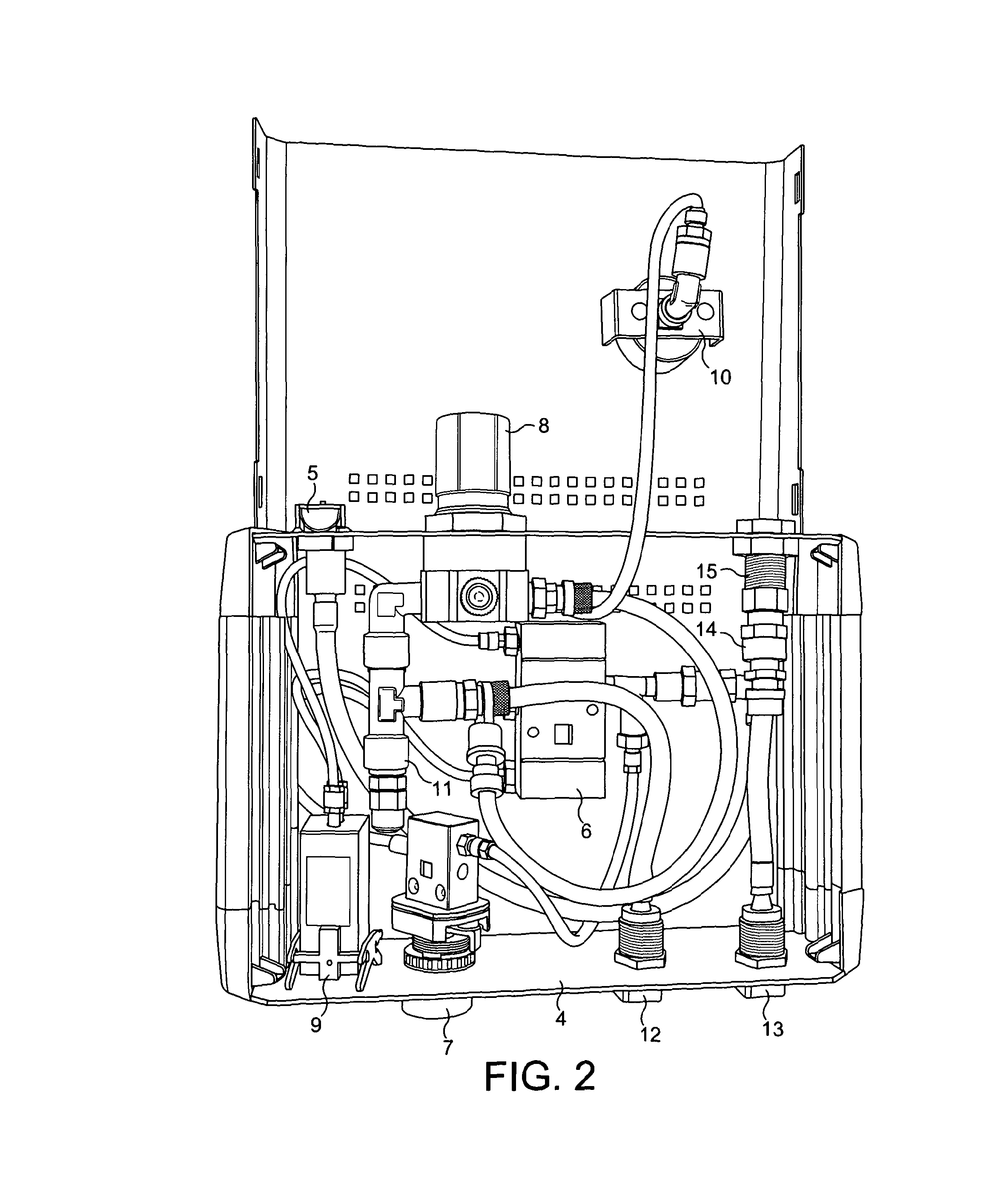
[0024]The apparatus according to the invention is shown diagrammatically in the top portion of FIG. 1 and illustrated in FIG. 2 which is a plan view, with the lid swung back, of a casing 4 containing the relevant components to carry out controlled purging of the storage container 1. The various components arranged on or in the casing 4. These include an inlet connector 5 which is connected to both a pneumatically actuated main control valve 6 and a trigger valve 7 mounted on the front panel of casing 4. Trigger valve 7 is connected to the main control valve 6, which is also conn...


PUM


Abstract

Apparatus for purging containers for the storage of sensitive materials is described. It includes means to connect a source of compressed purge gas to a purge gas inlet (2) on a container (1), including a pneumatically operated valve (6) adapted to allow purge gas to pass from the source to the inlet and a timing device (9) associated with the valve (6) and adapted to turn off the gas flow after a given time, and including means to vary the time between commencement and cessation of gas flow. The timing device is preferably one which operates on a pneumatic or clockwork basis, enabling the apparatus to operate without any electrical power supply, driven by the purge gas pressure alone. This enables the construction of a simple reliable unit, at a cost even enabling the unit to be incorporated into the container itself if desired. The use of a pneumatically operated valve enables portable apparatus to be designed with low power use if it includes e.g. electronic sensors to measure a property of the purge gas being exhausted from the container.

Description

FIELD OF THE INVENTION[0001]This invention relates to apparatus for purging containers for storing sensitive materials.BACKGROUND OF THE INVENTION[0002]WO 2006 / 095121 discloses apparatus and methods for storing sensitive materials in rigid sealable enclosures. After the sensitive materials, for example molecule compounds dissolved in DMSO, are placed in the enclosure, it is sealed and then purged using a purge gas and preferably left with the interior filled with inert gas at a pressure slightly above ambient so that if there is any problem with the sealing, the leakage occurs from the inside of the container to the outside rather than the other way round, which could lead to contamination and deterioration of the contents stored in the container.[0003]The published specification discloses containers adapted for use in the method as well as a control unit which enables them to be purged and left under excess pressure.[0004]The control unit described is adapted to detect the nature o...

Claims


Application Information

Patent Timeline
IPC IPC(8): H01L21/673F17D1/04
CPCF17D1/04H01L21/67393
Inventor NAYLOR, STUART
Owner ROYLAN DEV
Why Eureka
Try Eureka