
Lightning resistant gas tubing system

a technology of gas tubing and lightening, which is applied in the field of tubing systems, can solve the problems of csst covering and making visual inspection difficult, tubing is susceptible to puncture, and the risk of fire from leaking gas or explosion from pooled or accumulated gas, so as to achieve the effect of determining the integrity of the tubing system

Active Publication Date: 2019-06-25
GOODSON MARK EUGENE +1
View PDF20 Cites 0 Cited by
  • Summary
  • Abstract
  • Description
  • Claims
  • Application Information

AI Technical Summary

Benefits of technology

The system effectively mitigates electrical injuries by dissipating energy and providing indication of electrical insults, ensuring the integrity of the tubing without requiring full-length visual inspection, thus preventing damage and ensuring safety.

Problems solved by technology

Oftentimes CSST is installed in places where it is not able to be visually inspected after construction is completed.
In many cases where the CSST could be visible for inspection, the CSST is covered by insulation applied between joists, thereby covering the CSST and making visual inspection difficult.
Despite the advantages of CSST, the tubing is susceptible to puncture by an electrical injury.
When CSST is punctured, there is a risk of fire from the leaking gas or a risk of explosion from pooled or accumulated gas.
One type of electrical injury is damage caused by an electrical current passing through the object where the current is greater than the object can carry without damage.
These metallic components are not known for their ability to carry electric current.

Method used


Image

  • Lightning resistant gas tubing system
  • Lightning resistant gas tubing system
  • Lightning resistant gas tubing system

Examples


Embodiment Construction

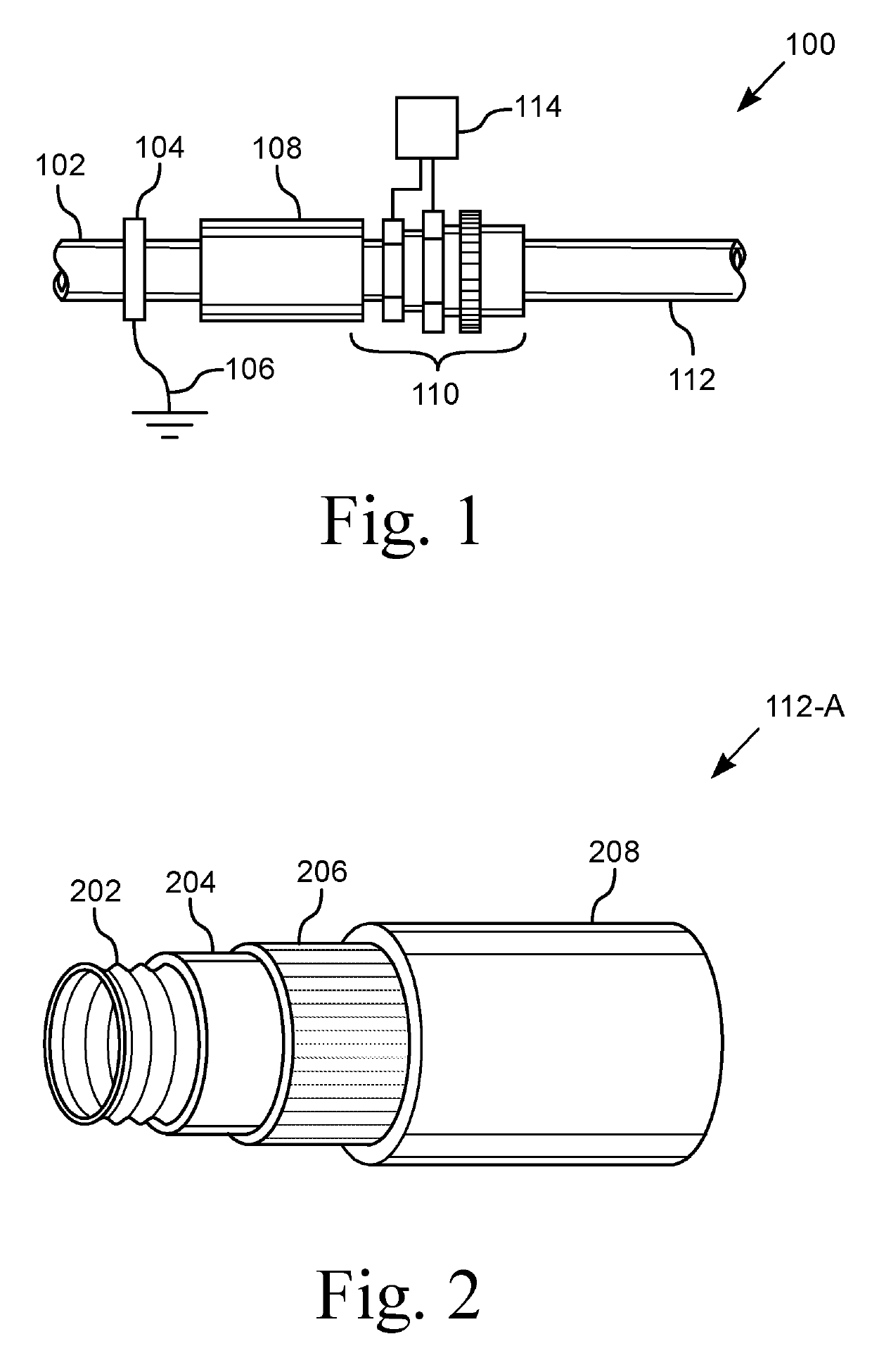
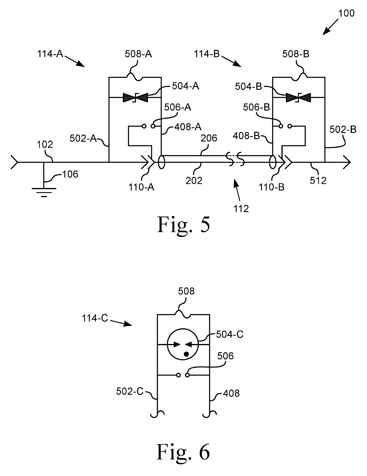
[0022]Apparatus for lightning resistant gas tubing is disclosed. The tubing system is generally indicated as 100. Various components are illustrated both generically and specifically in the figures and in the following description. For example, various embodiments of the transient voltage suppression (TVS) device 504 are discussed individually and separately to ensure clarity when describing the configuration of each embodiment of the TVS devices 504-A, 504-B, 504-C. The TVS 504, when referred to collectively, is referenced without the alphanumeric suffix.

[0023]FIG. 1 illustrates a partial side view of one embodiment of a supply pipe 102, a connector 110, and tubing 112. The tubing system 100 includes a length of tubing 112, at least one connector 110, and an electrical injury mitigator 114. In one embodiment, there is a connector 110 at each end of the tubing 112.

[0024]One end of the tubing system 100 is attached to a gas supply pipe or line 102. In various configurations the suppl...


PUM


Abstract

Apparatus for detecting an electrical insult to a gas tubing system and dissipating the energy from such insult. The system includes tubing, at least one terminating connector, and an injury mitigator. The tubing includes a conduit, an insulating layer, a conductive layer, and a jacket. The conduit is connected to earth ground. The conductive layer is electrically insulated from the conduit by the insulating layer. The mitigator includes an insult event detection circuit and an energy dissipation circuit, both electrically connected between the conductive layer of the tubing and ground. Insult indication is provided by a fusible link. Energy dissipation is provided by the fuse, a transient voltage suppression (TVS) device, and / or a spark gap. The TVS device has a setpoint voltage less than the breakdown voltage of the spark gap, ensuring that the TVS device actuates before the spark gap conducts.

Description

CROSS-REFERENCE TO RELATED APPLICATIONS[0001]This application claims the benefit of U.S. Provisional Application No. 62 / 451,678, filed Jan. 28, 2017.STATEMENT REGARDING FEDERALLY SPONSORED RESEARCH OR DEVELOPMENT[0002]Not ApplicableBACKGROUND1. Field of Invention[0003]This invention pertains to a tubing system that is resistant to lightning strikes. More particularly, this invention pertains to gas tubing that includes a conductive layer insulated from the fluid conduit, including connectors to the tubing.2. Description of the Related Art[0004]Corrugated stainless steel tubing (CSST) is a flexible, stainless steel pipe or conduit used to supply natural gas and propane in residential, commercial, and industrial structures. The tubing is routed inside structures between the walls and floors, under floors and / or above the ceiling. Oftentimes CSST is installed in places where it is not able to be visually inspected after construction is completed. In many cases where the CSST could be v...

Claims


Application Information

Patent Timeline
Patent Type & Authority Patents(United States)
IPC IPC(8): F16L11/118F16L5/10F17D5/08F16L25/01F16L11/15F16L9/06F16L19/04F16L25/00
CPCF16L11/1185F16L5/10F16L11/15F17D5/08F16L25/01F16L25/0036F16L9/06F16L19/041F16L11/127F16L25/023
Inventor GOODSON, MARK EUGENEICOVE, DAVID J.
Owner GOODSON MARK EUGENE
Learn More