
Electrophotographic member, process cartridge, and electrophotographic image forming apparatus

a technology of electrophotographic image and process cartridge, which is applied in the direction of electrographic process apparatus, optics, instruments, etc., can solve the problems of affecting image quality, removing toner components, and affecting the charge imparting property, so as to achieve stable formation of high-quality electrophotographic images, suppress the adhesion of toner components, and form high-quality electrophotographic images

Active Publication Date: 2019-06-04
CANON KK
View PDF47 Cites 12 Cited by
  • Summary
  • Abstract
  • Description
  • Claims
  • Application Information

AI Technical Summary

Benefits of technology

[0006]One aspect of the present disclosure is directed to providing an electrophotographic member which can suppress adhesion of the toner component to the surface even in the case of printing a large number of sheets. Another aspect of the present disclosure is directed to providing an electrophotographic process cartridge which contributes to the stable formation of a high-quality electrophotographic image. Still another aspect of the present disclosure is directed to providing an electrophotographic image forming apparatus which can stably form a high-quality electrophotographic image.

Problems solved by technology

The charging of toner greatly affects the image quality, and an insufficient triboelectric charging quantity of toner also causes fogging.
However, it is impossible to remove the toner component once adhered when a large number of sheets are printed, and as a result, the charging imparting property is likely to deteriorate and fogging occurs in some cases.

Method used


Image

  • Electrophotographic member, process cartridge, and electrophotographic image forming apparatus
  • Electrophotographic member, process cartridge, and electrophotographic image forming apparatus
  • Electrophotographic member, process cartridge, and electrophotographic image forming apparatus

Examples


example 1

[0088]1. Fabrication of Mandrel

[0089]A SUS 304 core grid having an outer diameter of 6 mm and a length of 279 mm was coated with a primer (trade name: DY 35-051, manufactured by Dow Corning Toray Co., Ltd.), and heated at a temperature of 150° C. for 20 minutes, thereby obtaining a mandrel as a support

[0090]2. Formation of Second Elastic Layer (Lower Layer)

[0091]The mandrel was placed in a cylindrical mold having an inner diameter of 12.0 mm so as to be concentric with the cylinder of the mold. As the material of the second elastic layer, an addition type silicone rubber composition in which the materials presented in the following Table 1 were mixed by using a mixer (product name: Trimix TX-15, manufactured by INOUE MFG., INC.) was injected into the mold heated to a temperature of 115° C. After injection of the materials, the composition was hot molded at a temperature of 120° C. for 10 minutes and the molded body was cooled to room temperature and then released from the mold, ther...

example 2

[0125]An electrophotographic member was prepared and evaluated in the same manner as in Example 1 except that an acrylic polyol (trade name: PLACCEL DC2016, manufactured by DAICEL CORPORATION) was used instead of “PX41-11” when forming the second region.

example 3

[0126]An electrophotographic member was prepared and evaluated in the same manner as in Example 1 except that a polyester-based polyol (trade name: P3010, manufactured by Kuraray Co., Ltd.) was used instead of polyester-based polyol P1012 (trade name, manufactured by Kuraray Co., Ltd.) when preparing the upper elastic layer.


PUM


Abstract

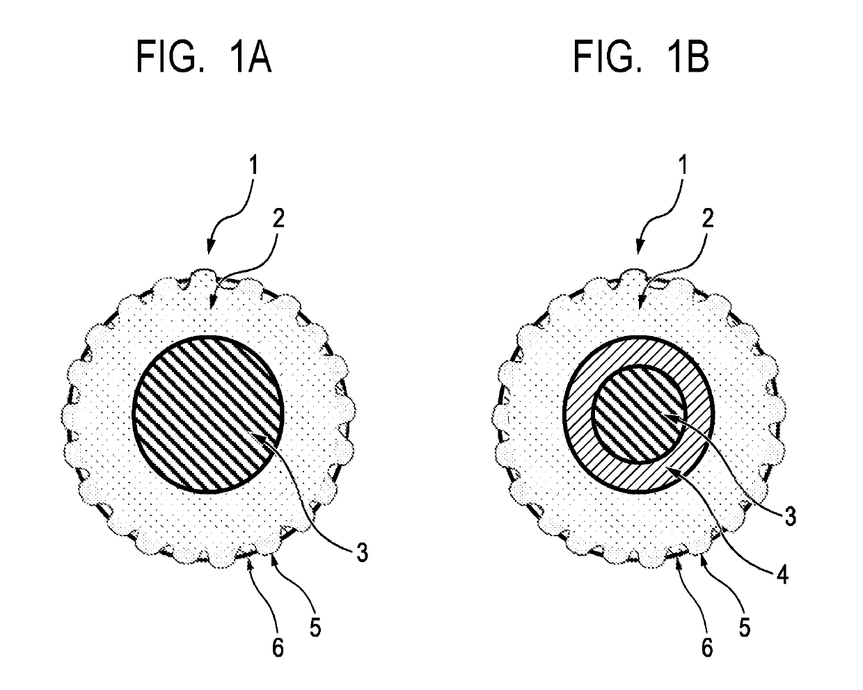
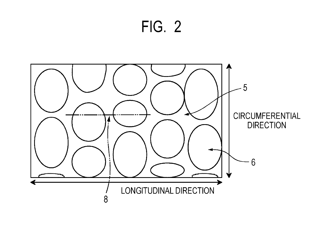
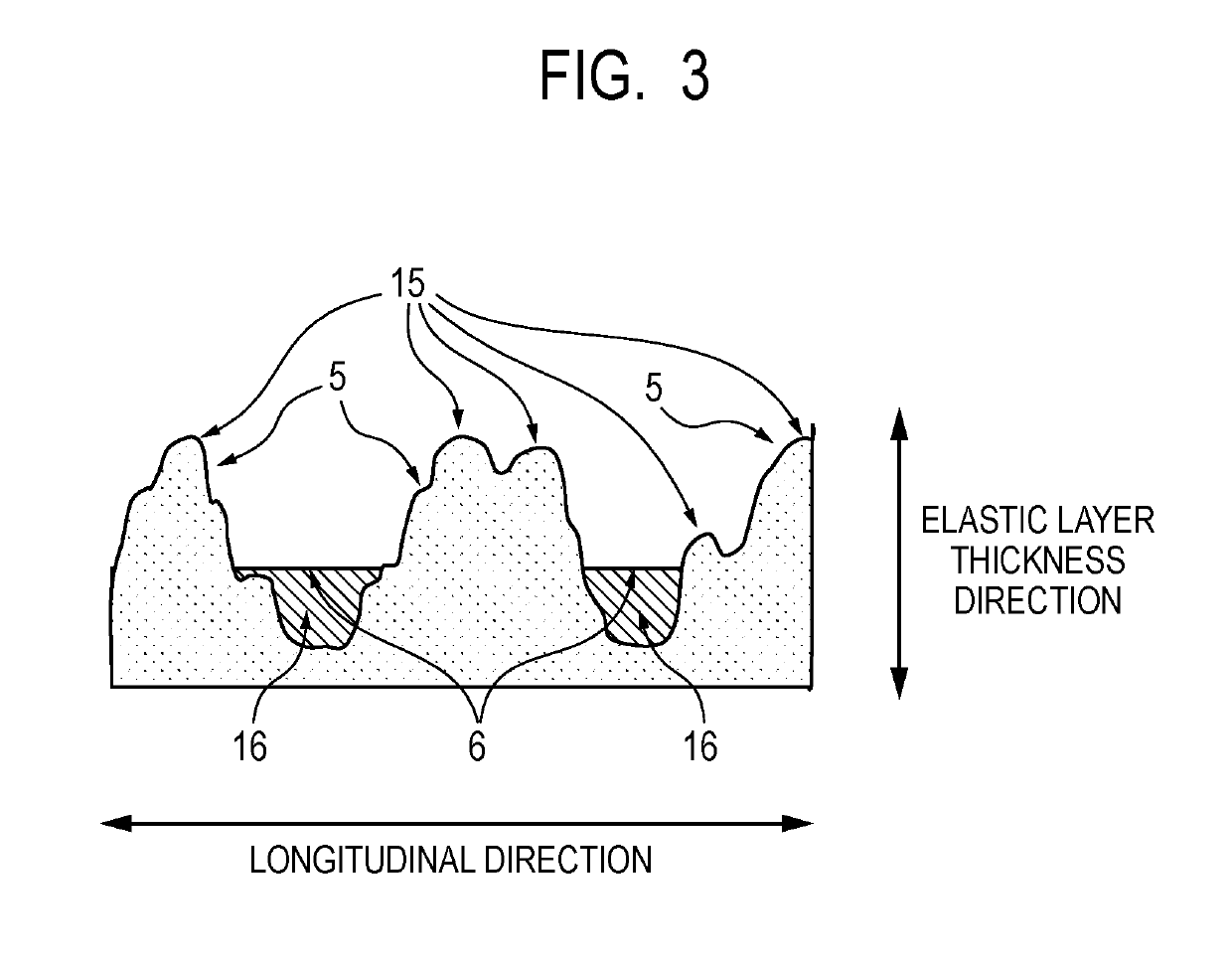
Provided is an electrophotographic member which can suppress adhesion of the toner component and fogging even in the case of printing a large number of sheets. The electrophotographic member includes an electroconductive support and an elastic layer and has convex portions composed of the elastic layer on a surface of the electrophotographic member and a filled portion containing a resin at a valley portion between the convex portions, the filled portion has a height lower than heights of the convex portions, and the surface of the electrophotographic member has a specific Martens hardness.

Description

BACKGROUND OF THE INVENTIONField of the Invention[0001]The present disclosure relates to an electrophotographic member which can be used as a developing member or a charging member in an electrophotographic image forming apparatus. The present disclosure also relates to a process cartridge and an electrophotographic image forming apparatus.Description of the Related Art[0002]In recent years, electrophotographic image forming apparatuses such as copying machines, facsimile machines, and printers are required to exhibit higher durability than ever before.[0003]In the process of forming an image in the electrophotographic image forming apparatus, the developing member plays a role of transporting the toner and imparting a charge to the toner. The charging of toner greatly affects the image quality, and an insufficient triboelectric charging quantity of toner also causes fogging. Hence, the developing member is required to exhibit improved toner contamination resistance than ever before...

Claims


Application Information

Patent Timeline
Patent Type & Authority Patents(United States)
IPC IPC(8): G03G15/08G03G21/18G03G5/04
CPCG03G21/1814G03G15/0818G03G15/0808G03G5/04G03G15/0233
Inventor MORISHITA, HIROSHISAKURAI, YUJIISHIDA, KAZUTOSHINAKAMURA, MINORUISHII, TORUSUGIYAMA, RYOMATSUNAGA, KENTA
Owner CANON KK
Learn More