
Fastener and method of sealing passage

a fastener and sealing passage technology, applied in the field of fasteners, can solve the problems of essentially dry mines, reduced integrity of tunnels or shafts, and leakage that can penetrate into tunnels or space between tubing rings, and achieve the effect of limiting or preventing leakage and being practical and effectiv

Active Publication Date: 2019-06-04
RELBORGN +1
View PDF19 Cites 3 Cited by
  • Summary
  • Abstract
  • Description
  • Claims
  • Application Information

AI Technical Summary

Benefits of technology

Effectively reduces leakage by allowing the introduction of grout or sealant into the passage between tubbing components, ensuring a watertight seal and enhancing the structural integrity of the tunnel or shaft, even in existing constructions.

Problems solved by technology

One problem that persists is leakage that can penetrate into the tunnel or into space between tubbing rings via leaks in or at the bolts that hold tubbing segments and / or tubbing rings together, or which attach flanges of tubbing to the tunnel wall.
Since these bolts are part of the final structure of the tubbing and hence the constructed tunnel, they remain in place for the duration of the life of the tunnel and so leakage through these points can lead to a persistent problem that diminishes the integrity of the tunnel or shaft.
How large a problem this leaking turns out to be depends on the amount of leakage through each bolt join and the number of bolt joins in any tubbing housing that develop a leak.
However, even in the context of different mine excavations, the nature of the mineral involved may dictate that the mine be essentially completely dry.
Further, some tunnel situations may require longevity of grouting application in preventing water inflow.
In these situations, standard cement-based grouting techniques may be less than optimal.

Method used


Image

  • Fastener and method of sealing passage
  • Fastener and method of sealing passage

Examples


Embodiment Construction

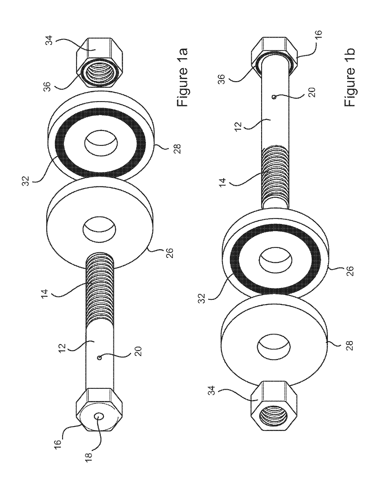
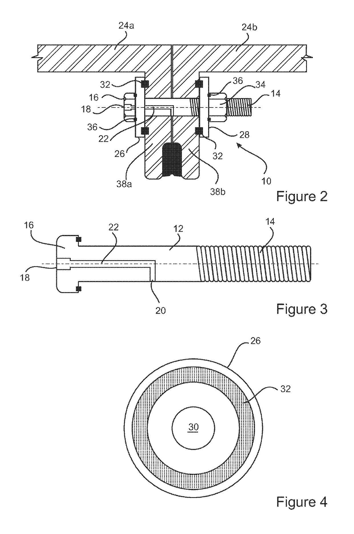
[0029]It will now be convenient to describe the present invention with reference to the accompanying drawings. It should be understood that the following description is illustrative of explanatory embodiments of the present invention and should not be taken as limiting the scope of the invention to any one embodiment. Further, the Figures depicted in this specification have been included for illustrative purposes only and are not intended to be limiting. It will be understood by the relevant skilled addressee that the embodiments described are typical and illustrative only and can be varied without departing from the scope of the invention.

[0030]Referring initially to FIGS. 1a and 1b, there is shown a fastener 10 for typical use in fastening together two components. In the embodiment described, the fastener 10 is described in the context of the application of fastening adjacent tubbing segments, 24a and 24b or tubbing rings used in construction of excavated tunnels and shafts. Howev...


PUM


Abstract

A fastener for fastening adjacent portions of a structure requiring fastening is described. The present fastener enables delivery of grout or a sealing composition into a passage between or adjacent the portions of the structure or between adjacent parts of the structure. The portions of the structure may include tubbing rings and segments thereof. The fastener includes an inlet and at least one outlet. The inlet and at least one outlet are connected by a channel. Grout or sealing composition can be delivered into the inlet where it flows through the channel, outwardly through the at least one outlet and into the passage requiring sealing. A method of sealing a passage in a formation using the fastener is also described.

Description

CROSS-REFERENCE TO RELATED APPLICATIONS[0001]This application is a national phase filing of International patent application No. PCT / IB2014 / 059648, filed on Mar. 12, 2014, which is herein incorporated by reference in its entirety.FIELD OF THE INVENTION[0002]The present invention relates to a fastener for fastening tubbing segments and tubbing rings. The fastener is adapted to facilitate introduction of grout or sealant for purposes of sealing openings, fissures and the like in surrounding structures, strata and / or between tubbing segments and rings. The present invention also includes a method of sealing incorporating the fastener.BACKGROUND TO THE INVENTION[0003]Various types of tubbings are known to the art of tunnel or shaft construction. Tubbing typically comprises a lining of metal around the shaft of an excavation, such as a shaft of a mine or tunnel. Tubbing segments are assembled on site into tubbing rings, joined by bolts and typically compressed with concrete. The tubbing ...

Claims


Application Information

Patent Timeline
Patent Type & Authority Patents(United States)
IPC IPC(8): F16B1/00F16B33/00F16B43/00E21D11/08F16B29/00E21D5/10F16B5/02
CPCE21D5/10E21D11/083F16B33/004F16B43/001F16B29/00F16B5/02
Inventor VAN DYK, DEON
Owner RELBORGN
Learn More