Control of an RO installation for flushing solutions

Active Publication Date: 2019-06-04
VOLKER MANFRED
View PDF26 Cites 0 Cited by
  • Summary
  • Abstract
  • Description
  • Claims
  • Application Information

AI Technical Summary

Benefits of technology

The invention aims to create a system that can produce a pure liquid cleaning solution using filter technology from tap water. The solution should be cost-effective, contain no toxic substances, and have a long lifespan. The system should also be reliable and fail safe, with maintenance and control of the membrane necessary. The invention uses electronics and software for monitoring and controlling the efficiency of the system, allowing for the detection and prevention of issues that could affect the quality of the liquid produced.

Problems solved by technology

A verifiable liquid quality is to be achieved and the expense necessary for the purification steps and toxic substances is to be limited.

Method used


Image

  • Control of an RO installation for flushing solutions
  • Control of an RO installation for flushing solutions
  • Control of an RO installation for flushing solutions

Examples


Embodiment Construction

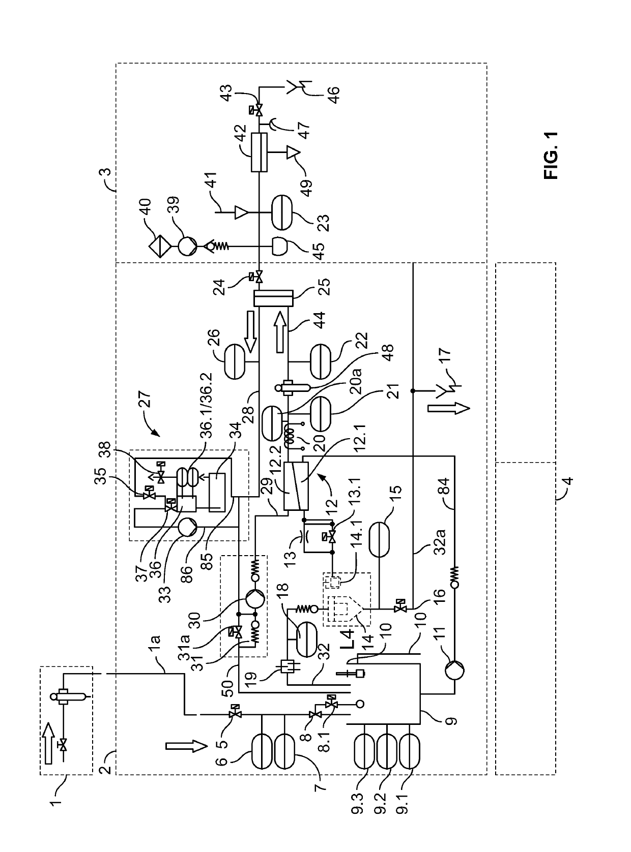
[0083]FIG. 1 is a view showing the underlying principle.

[0084]Further exemplary embodiments and an indication of possible variants and extensions are shown in FIG. 1 at the same time. Detailed information is given in more detail in the subsequent figures.

[0085]The liquid is conducted via an optional pre-filter (1) to the RO installation (2). In the inlet region of the RO installation there is a water inlet valve (5), an inflow flow meter (7) and an inlet conductivity meter (6). The supplied liquid flows via a float-controlled inlet valve (8) via the feed container (9), which is equipped with filling level sensors for determining when it is empty and for filling level control (9.1, 9.2, 9.3).

[0086]The float-controlled inlet valve is constructed in the form of a membrane servo valve, the servo bore of which can be closed by extremely low buoyancy forces, that is to say very small float volumes, and thus controls the filling level. There is furthermore the possibility of interrupting t...


PUM


Abstract

The method of verifying an RO membrane of an RO installation is characterized in that the conductivity values of the supplied raw water and of the permeate and the amount of the raw water inflow and the concentrate outflow are continuously or cyclically measured and that the efficiency of the RO membrane, its retention rate and / or filtration efficiency are calculated from the measured values.

Description

FIELD OF THE INVENTION[0001]The subject application relates to medical flushing solutions, and more particularly to a control of a reverse osmosis (RO) installation for flushing solutions.SUMMARY OF THE INVENTION[0002]The object of this development is to produce an economical, chemically and microbiologically ultrapure liquid de-centrally in situ as a base material for the use of medicinal flushing solutions from (pre-treated) tap water by the use of filter technology in order to achieve economic and application-technical advantages.[0003]A verifiable liquid quality is to be achieved and the expense necessary for the purification steps and toxic substances is to be limited. An environmentally friendly technology and an intelligent evaluation of the data are to improve the service life of the components used or detect their wear in a timely manner.[0004]Use of this development for other fields, such as liquid preparation for the laboratory, for biology and pharmacy as an ultrapure fl...

Claims


Application Information

Patent Timeline
IPC IPC(8): B01D65/10B01D61/02B01D61/08B01D61/12G01N27/08G01N27/12G01N15/08C02F1/44C02F103/02C02F103/04
CPCB01D65/10B01D61/025B01D61/08B01D61/12C02F1/441G01N15/08G01N27/08G01N27/12B01D61/02G01N2015/086B01D2311/243B01D2311/25C02F1/444C02F2103/026C02F2103/04C02F2209/02C02F2209/03C02F2209/05C02F2209/40C02F2209/42B01D2311/2512
Inventor VOLKER, MANFRED
Owner VOLKER MANFRED
Why Eureka
Try Eureka