
Control apparatus for internal combustion engine

a control apparatus and internal combustion engine technology, applied in the direction of electric control, ignition automatic control, machines/engines, etc., can solve the problems of deterioration in fuel economy deterioration in drivability, etc., to suppress the deterioration in drivability of the vehicle and the effect of fuel economy deterioration

Active Publication Date: 2019-05-21
TOYOTA JIDOSHA KK
View PDF7 Cites 0 Cited by
  • Summary
  • Abstract
  • Description
  • Claims
  • Application Information

AI Technical Summary

Benefits of technology

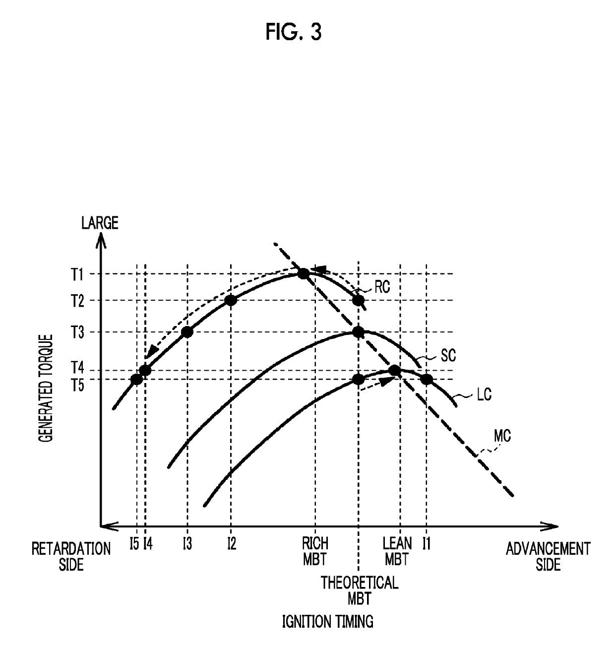
[0005]In the temperature raising process of Japanese Patent Application Publication No. 2012-057492 (JP 2012-057492 A) as well, the torque generated in each rich cylinder increases, and the torque generated in each lean cylinder decreases, so torque fluctuations are caused. As a result, the amplitude of vibrations of the internal combustion engine may increase to cause a deterioration in drivability. Therefore, as in Japanese Patent Application Publication No. 6-137242 (JP 6-137242 A), it is conceivable to restrain the internal combustion engine from vibrating by correcting the ignition timing in a retarding manner such that the torque generated in each rich cylinder is restrained from increasing, and correcting the ignition timing in an advancing manner such that the torque generated in each lean cylinder is restrained from decreasing. However, when the ignition timing in each rich cylinder is corrected to be retarded to such an extent that the difference between the torque generated in each rich cylinder and the torque generated in each lean cylinder becomes sufficiently small with a view to restraining the internal combustion engine from vibrating, the torque generated in each rich cylinder may substantially decrease to cause a deterioration in fuel economy.
[0006]Thus, in view of the aforementioned circumstances, the disclosure provides a control apparatus for an internal combustion engine that also suppresses the deterioration in fuel economy while suppressing the deterioration in drivability.
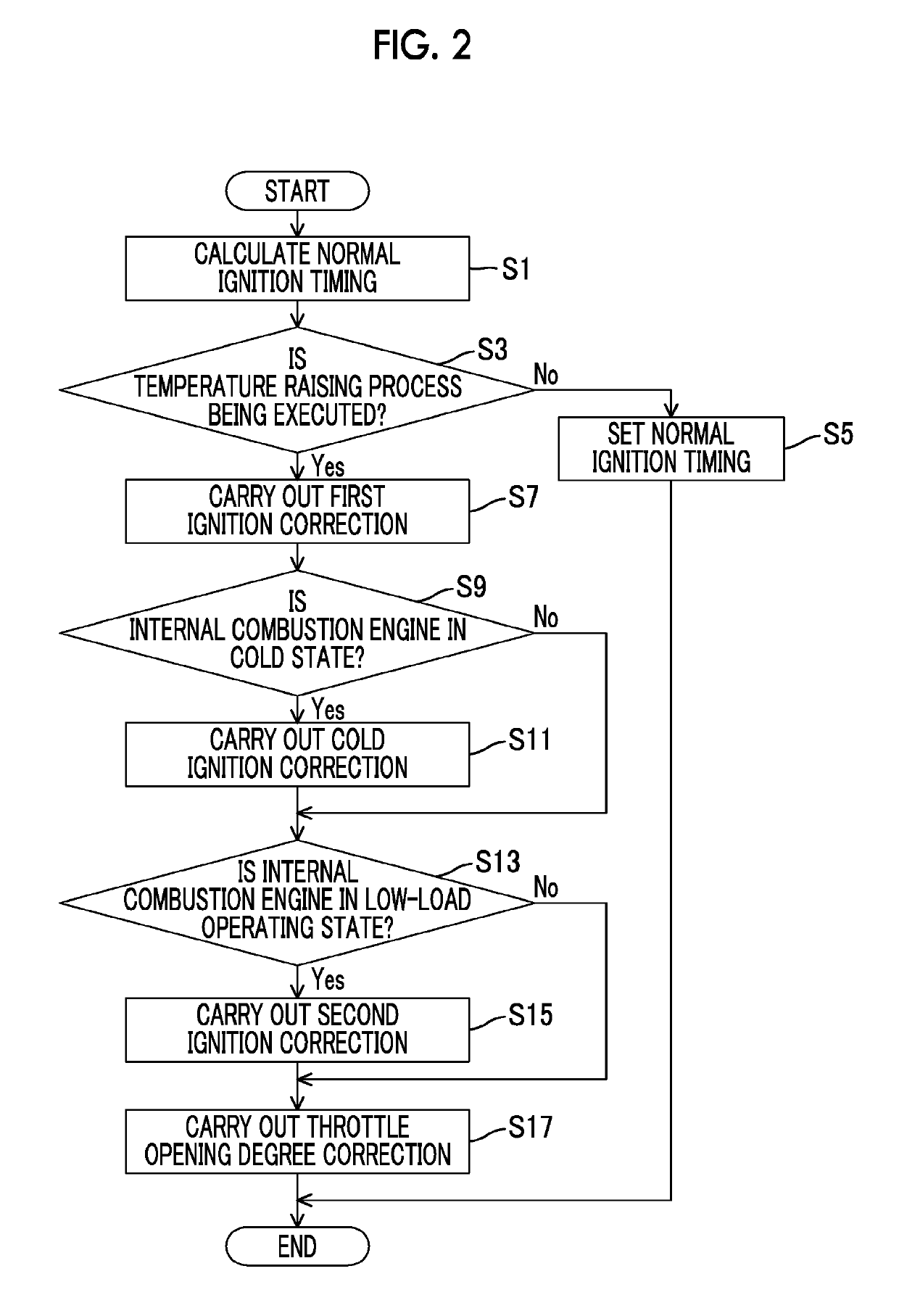
[0008]In the case where the internal combustion engine is in the low-load operating state, the internal combustion engine is in, for example, idling operation. A driver is considered to be likely to recognize vibrations of the internal combustion engine resulting from the execution of the temperature raising process. Therefore, according to the control apparatus for the internal combustion engine as described above, the respective ignition timings are corrected such that the torque generated in the rich cylinder decreases and the torque generated in each of the lean cylinders increases, in the low-load operating state. Therefore, the generated torque can be restrained from fluctuating between the rich cylinder and each of the lean cylinders, and the deterioration in drivability can be suppressed. Besides, in this case, the torque generated in the rich cylinder decreases to cause a deterioration in fuel economy. In the low-load operating state, however, the amount of fuel consumption is small in the first place, so the influence on the deterioration in fuel economy is small. On the other hand, in the case of a state other than the low-load operating state, for example, an intermediate-load operating state or a high-load operating state in which the vehicle runs at high speed, the driver is considered to be less likely to recognize vibrations of the internal combustion engine resulting from the execution of the temperature raising process than in the case of the low-load operating state. Besides, in the intermediate-load operating state or the high-load operating state, it is desirable to suppress the deterioration in fuel economy by ensuring the output of the internal combustion engine. Therefore, the respective ignition timings are corrected such that the respective torques generated in the rich and lean cylinders increase, so the deterioration in fuel economy can be suppressed.
[0014]As described above, the control apparatus for the internal combustion engine according to the disclosure can also suppress the deterioration in fuel economy while suppressing the deterioration in drivability of the vehicle.

Problems solved by technology

As a result of such fluctuations in the rotational speed, the amplitude of vibrations of the internal combustion engine may increase to cause a deterioration in drivability.
As a result, the amplitude of vibrations of the internal combustion engine may increase to cause a deterioration in drivability.
However, when the ignition timing in each rich cylinder is corrected to be retarded to such an extent that the difference between the torque generated in each rich cylinder and the torque generated in each lean cylinder becomes sufficiently small with a view to restraining the internal combustion engine from vibrating, the torque generated in each rich cylinder may substantially decrease to cause a deterioration in fuel economy.
A driver is considered to be likely to recognize vibrations of the internal combustion engine resulting from the execution of the temperature raising process.
Besides, in this case, the torque generated in the rich cylinder decreases to cause a deterioration in fuel economy.
In the low-load operating state, however, the amount of fuel consumption is small in the first place, so the influence on the deterioration in fuel economy is small.

Method used


Image

  • Control apparatus for internal combustion engine
  • Control apparatus for internal combustion engine
  • Control apparatus for internal combustion engine

Examples


Embodiment Construction

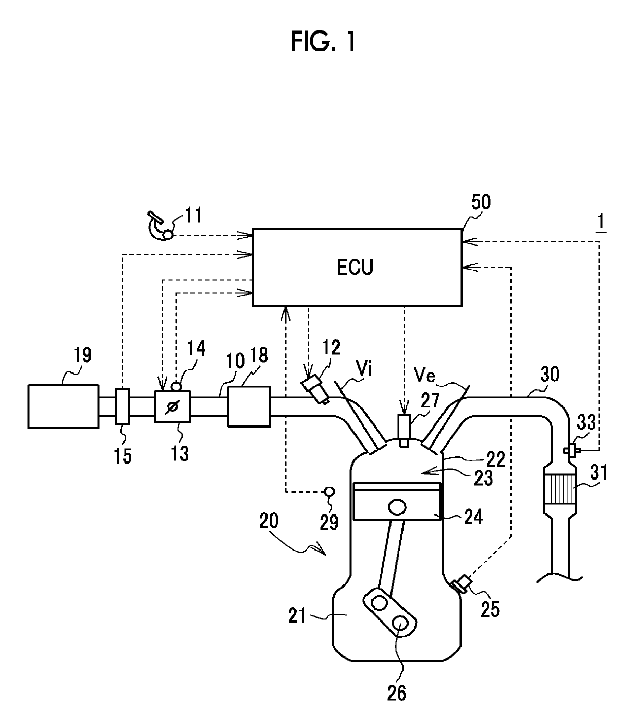
[0027]FIG. 1 is a schematic configuration view of a vehicle 1. The vehicle 1 is mounted with an internal combustion engine (hereinafter referred to as an engine) 20 as a motive power source for running, and is also mounted with a three-way catalyst 31 that purifies exhaust gas from the engine 20. In the engine 20, an air-fuel mixture is burned in a combustion chamber 23 of a cylinder head 22 that is arranged on an upper portion of a cylinder block 21, and a piston 24 is thereby moved in a reciprocating manner. The engine 20 is an in-line four-cylinder engine having four cylinders, but is not limited thereto as long as it has a plurality of cylinders.

[0028]An intake valve Vi that opens / closes an intake port, and an exhaust valve Ve that opens / closes an exhaust port are provided for each of the cylinders in the cylinder head 22 of the engine 20. Besides, an ignition plug 27 for igniting the air-fuel mixture in the combustion chamber 23 is attached to a top portion of the cylinder head...


PUM


Abstract

In a control apparatus for an internal combustion engine, The ignition timing in a rich-cylinder is corrected toward a retardation side from a theoretical-MBT such that the torque generated in the rich-cylinder exceeds a torque generated in the rich-cylinder at the theoretical-MBT, and the ignition timing in a lean-cylinder is corrected toward an advancement side from the theoretical-MBT such that the torque generated in the lean-cylinder exceeds a torque generated in the lean-cylinder at the theoretical-MBT, when a temperature raising process is being executed, and the ignition timing in the rich-cylinder is corrected further toward the retardation side such that the torque generated in the rich-cylinder becomes equal to or smaller than a maximum theoretical generated torque and equal to or larger than the torque generated in the lean-cylinder at the theoretical-MBT, when the temperature raising process is being executed and the engine is in a low-load operating state.

Description

CROSS-REFERENCE TO RELATED APPLICATIONS[0001]This application claims priority to Japanese Patent Application No. 2016-252101 filed on Dec. 26, 2016, which is incorporated herein by reference in its entirety.BACKGROUND1. Technical Field[0002]The disclosure relates to a control apparatus for an internal combustion engine.2. Description of Related Art[0003]There is known a temperature raising process for raising the temperature of a catalyst to a temperature at which the catalyst is activated or regenerated to suppress the deterioration in emission properties of exhaust gas from an internal combustion engine. For example, it is described in Japanese Patent Application Publication No. 2012-057492 (JP 2012-057492 A) that at least one of a plurality of cylinders of an internal combustion engine is controlled to a rich cylinder whose air-fuel ratio is rich, and each of the other remaining cylinders is controlled to a lean cylinder whose air-fuel ratio is lean, as the temperature raising pr...

Claims


Application Information

Patent Timeline
Patent Type & Authority Patents(United States)
IPC IPC(8): F02D41/02F02P5/04F02D41/34F02D41/14F02D41/00F02D41/30F02D9/02F02D11/10F02P5/15
CPCF02D41/024F02D11/105F02D41/0002F02D41/0082F02D41/1475F02D41/3005F02D41/34F02P5/045F02P5/1512F02P5/1514F02D9/02Y02T10/46F02D2009/0237F02D2200/602Y02T10/26Y02T10/42Y02T10/44F02D41/1454F02P5/15Y02T10/12Y02T10/40
Inventor NOSE, YUKISHOGENJI, YOSHIYUKIIKUTA, EIJIMYOJO, KEIICHI
Owner TOYOTA JIDOSHA KK
Learn More