Coil device and wireless power transmission device
- Summary
- Abstract
- Description
- Claims
- Application Information
AI Technical Summary
Benefits of technology
Problems solved by technology
Method used
Image

Examples
first embodiment
(The First Embodiment)
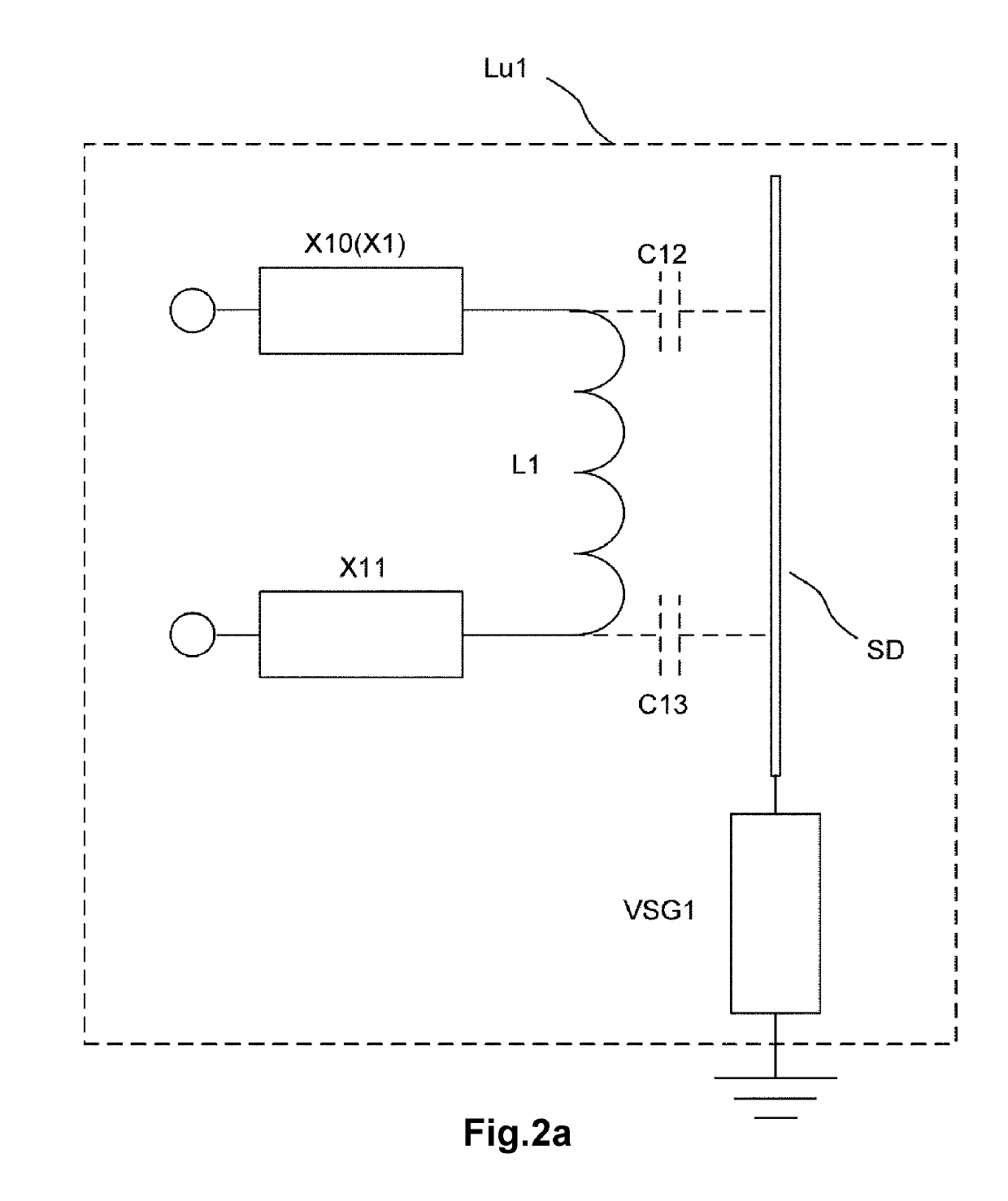
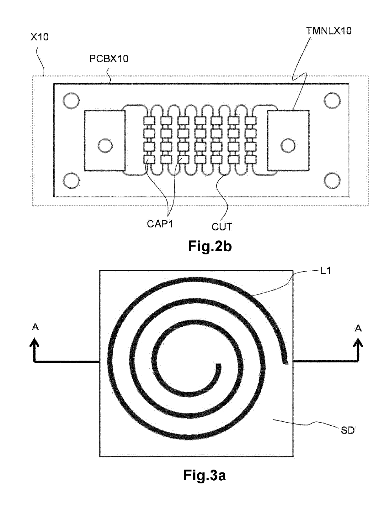
[0035]The construction of coil device Lu1 of the first embodiment of the present invention is described specifically referring to FIG. 2 and FIG. 3. FIG. 2a is a schematic view showing the circuit construction of the coil device according to the first embodiment of the present invention. FIG. 2b is a schematic view showing the construction of the first capacitor circuit in the coil device according to the first embodiment of the present invention. FIG. 3a is a plan view of the coil device according to the first embodiment of the present invention. FIG. 3b is a cross-sectional view of the coil device taken along cutting line A-A in FIG. 3a. Further, in FIG. 3a and FIG. 3b, the capacitor circuit is omitted for the convenience in description.
[0036]Coil device Lu1 comprises coil for power transmission L1, metal portion SD, capacitor circuit X1 and measuring portion VSG1 as shown in FIG. 2a.
[0037]Coil for power transmission L1 is constructed by winding the winding ...
second embodiment
(The Second Embodiment)
[0049]In the following, the coil device according to the second embodiment of the present invention is described. The construction of the coil device according to the second embodiment is the same as coil device Lu1 according to the first embodiment. In the coil device according to the second embodiment, a combined electrostatic capacity of first capacitor circuit X10 connected to one end of coil for power transmission L1 is approximately equal to a combined electrostatic capacity of second capacitor circuit X11 connected to the other end of coil for power transmission L1. Herein, in an ideal state, it is preferable that a combined electrostatic capacity of first capacitor circuit X10 and a combined electrostatic capacity of second capacitor circuit X11 is the same, however, the differences caused by the tolerance of a plurality of capacitor elements constituting first and second capacitor circuit X10 and X11 or the errors produced during the manufacturing of ...
third embodiment
(The Third Embodiment)
[0052]Hereinafter, the coil device according to the third embodiment of the present invention is described specifically referring to FIG. 5. FIG. 5 is a schematic view showing the construction of the first capacitor circuit in the coil device according to the third embodiment of the present invention. The construction of the coil device according to the third embodiment is the same as coil device Lu1 according to the first embodiment. The coil device according to the third embodiment is different from that of the first embodiment in the point that the constructions of a plurality of capacitor elements CAP1 constituting first and second capacitor circuits X10 and X11 (capacitor circuit X1) are different. In addition, as the constructions of first capacitor circuit X10 and second capacitor circuit X11 are the same, thus, only the construction of first capacitor circuit X10 will be described here.
[0053]First capacitor circuit X10 is constituted by mounting a plura...
PUM
 Abstract
Description
Claims
Application Information
 - R&D
- Intellectual Property
- Life Sciences
- Materials
- Tech Scout
- Unparalleled Data Quality
- Higher Quality Content
- 60% Fewer Hallucinations
Browse by: Latest US Patents, China's latest patents, Technical Efficacy Thesaurus, Application Domain, Technology Topic, Popular Technical Reports.
© 2025 PatSnap. All rights reserved.Legal|Privacy policy|Modern Slavery Act Transparency Statement|Sitemap|About US| Contact US: help@patsnap.com