Power generation input device and electronic-apparatus using the power generation input device

Active Publication Date: 2013-01-10
ALPS ALPINE CO LTD
View PDF10 Cites 7 Cited by
  • Summary
  • Abstract
  • Description
  • Claims
  • Application Information

AI Technical Summary

Benefits of technology

The power generation input device described in this patent is designed to increase power generation efficiency by naturally accelerating the rotation of the rotating body when it rotates to different postures. This is achieved by magnetically attracting two magnetization members to two opposite ends of a magnetic path forming member, which results in a large change in magnetic flux in the member over time. Additionally, the device is designed to have a gap between the magnetization members and the opposing end of the magnetic path forming member, which reduces the force required to rotate the rotating body. This makes the device easy to operate.

Problems solved by technology

Thus, the orientation of the magnetic flux in the core is not reversed, an amount of change of the magnetic flux in the core is small and the power generation efficiency is poor.
In the structure, when the magnet is inserted in the space, the magnet is attracted to an end of the core and moves at a relatively fast speed; however, when the magnet is withdrawn from the space, since a force acts in an orientation where the magnet is prevented from withdrawing from the magnet, there is a limit to the speed up the withdrawal.
In order to increase the electromotive force, a return spring is required to exert a strong force to withdraw the magnet from the space; however, the force of the return spring acts as a resistance against the operating force and the device is hard to operate.
If an excessive operating force is not provided, the device cannot be operated.

Method used


Image

  • Power generation input device and electronic-apparatus using the power generation input device
  • Power generation input device and electronic-apparatus using the power generation input device
  • Power generation input device and electronic-apparatus using the power generation input device

Examples


Embodiment Construction

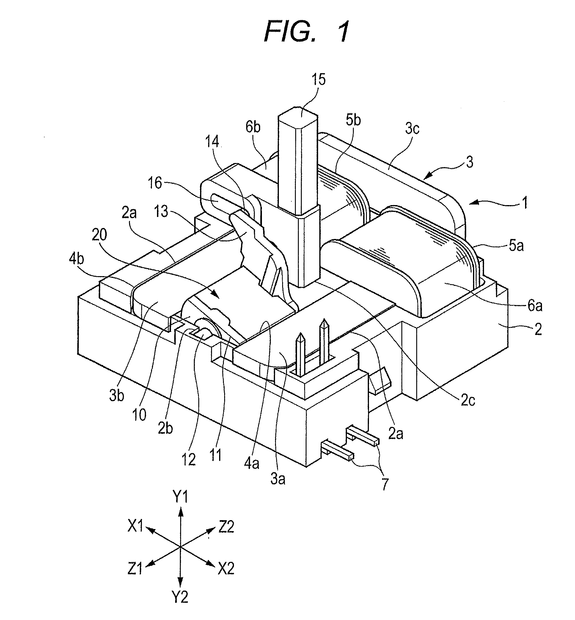
[0024]A power generation input device 1 shown in FIG. 1 has a housing 2. The housing 2 shown in FIG. 1 is a lower housing and an upper housing (not shown) is disposed on the housing 2.

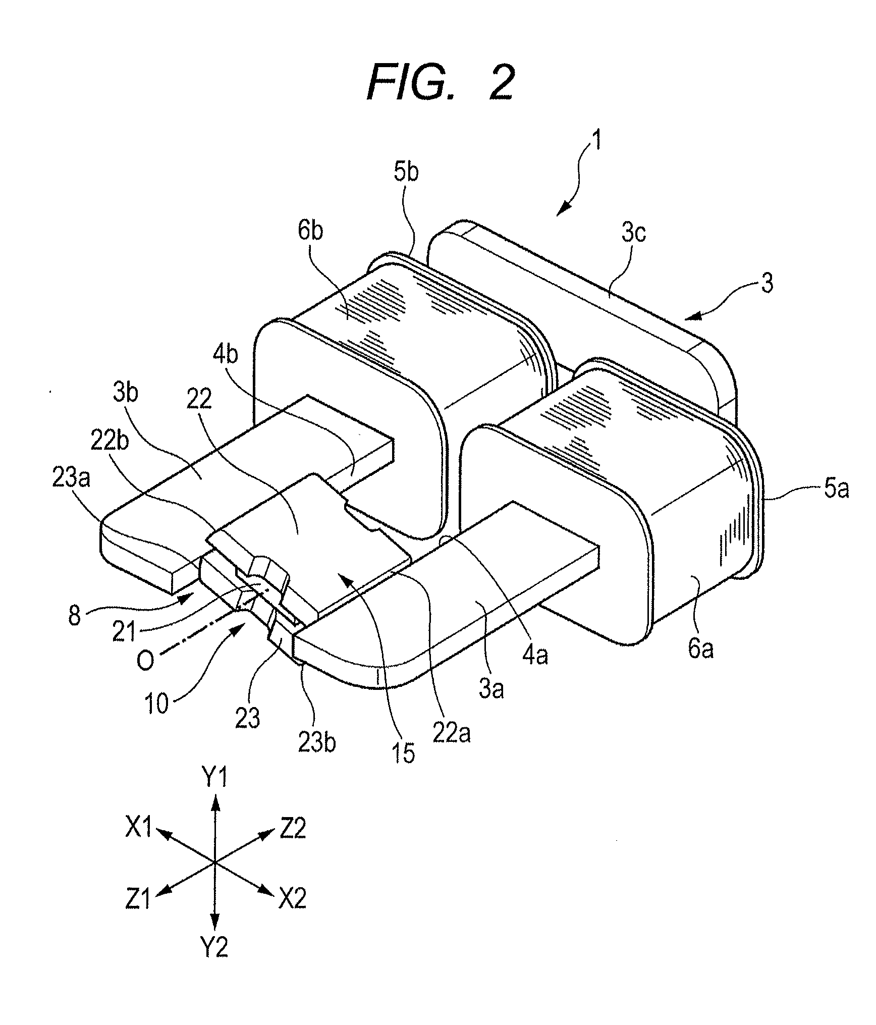
[0025]A magnetic path forming member 3 is held in the housing 2. As shown in FIG. 2, the magnetic path forming member 3 is configured such that a first arm portion 3a, a second arm portion 3b and a coupling portion 3c are integrally formed in succession. The U-shaped the magnetic path forming member 3 is formed of a soft magnetic metal plate and the coupling portion 3c is bent substantially at a right angle upward.

[0026]The first arm portion 3a has a first opposing end 4a and the second arm portion 3b has a second opposing end 4b.

[0027]In FIGS. 1 to 4, the opposing direction along plate surfaces of the first arm portion 3a and the second arm portion 3b is shown in X direction, and the thickness direction of the plates of the first arm portion 3a and the second arm portion 3b is shown in Y direction or...


PUM


Abstract

First and second opposing ends are formed in a magnetic path forming member on which a power generation coil is wound. A rotating body has a permanent magnet, a first magnetization member and a second magnetization member. When an operating force does not act on an operating member, an end surface of the first magnetization member is opposed to the first opposing end via a gap and an end surface of the second magnetization member is opposed to the second opposing end via a gap. When the operating member is pressed, the rotating body rotates and when the force to the operating member is released, the operating member and the rotating body return. Since the rotating body and the magnetic path forming member do not come into contact with each other, the force required to operate the operating member is relatively weak and large electromotive force can be obtained.

Description

CLAIM OF PRIORITY[0001]This application claims benefit of Japanese Patent Application No. 2011-150605 filed on Jul. 7, 2011, which is hereby incorporated by reference in its entirety.BACKGROUND[0002]1. Field of the Disclosure[0003]The present disclosure relates to a power generation input device which can generate power according to an operating force from the outside, and to an electronic apparatus where a transmitting operation or the like is performed according to the electromotive force of the power generation input device when it is operated.[0004]2. Description of the Related Art[0005]In FIG. 7 of Japanese Unexamined Patent Application Publication No. 2009-199961, a basic structure of a self-power generating type key input device is disclosed.[0006]The key input device includes a core forming a magnetic path and a coil portion wound on the core. Both ends of the core are opposed to each other via a space and a rod-shaped magnet can be interposed in the space. The electromotive...

Claims


Application Information

Patent Timeline
IPC IPC(8): H02M7/06
CPCH02M7/068H02M7/06H01F7/122H01F7/14
Inventor INADA, YUJISUZUKI, KATSUTOSHI
Owner ALPS ALPINE CO LTD
Why Eureka
Try Eureka