
Automated testing apparatus

a testing apparatus and automatic technology, applied in the direction of material analysis, optical elements, instruments, etc., can solve the problems of high magnification ratio of microscope equipment, excessive time and expense, and the inability to perform individual testing activities, etc., to achieve convenient use, less labor for testing, and less expensive

Active Publication Date: 2019-05-07
BONRAYBIO
View PDF59 Cites 20 Cited by
  • Summary
  • Abstract
  • Description
  • Claims
  • Application Information

AI Technical Summary

Benefits of technology

The invention provides a testing equipment with magnifying function that is cheaper and easier to use than conventional equipment. It can be used for various testing purposes such as semen testing, micro-organism testing, and body fluid analysis. The equipment has a simple structure and offers a cost-effective alternative to laboratory microscope equipment. It can be used at home and provides an instant result. The technology can also be integrated with existing intelligent communication devices such as smartphones or tablets, which can capture and transfer testing images. This offers an easy and affordable way to perform testing for various purposes.

Problems solved by technology

Currently, testing of liquid contents, are typically consigned to professional testing authorities for performing testing using expensive microscope equipment with high magnification ratios.
Since an individual does not have microscope equipment, the testing activity cannot be performed by the individual.
However, in some testing categories nowadays testing is required to be performed on a regular basis; therefore the need for frequent testing poses an excessive burden in terms of time and expense.
However, an individual cannot perform the semen testing by himself because the industry have not yet developed a technology that allows an individual to perform testing through a simple aiding device.

Method used


Image

  • Automated testing apparatus
  • Automated testing apparatus
  • Automated testing apparatus

Examples


Embodiment Construction

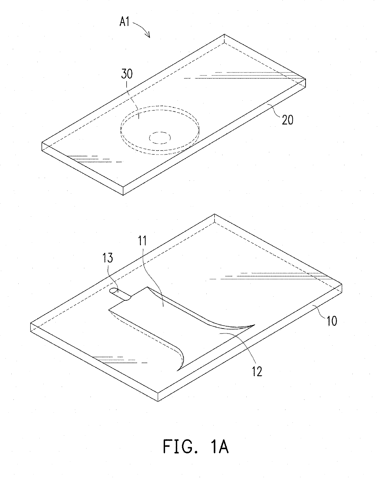
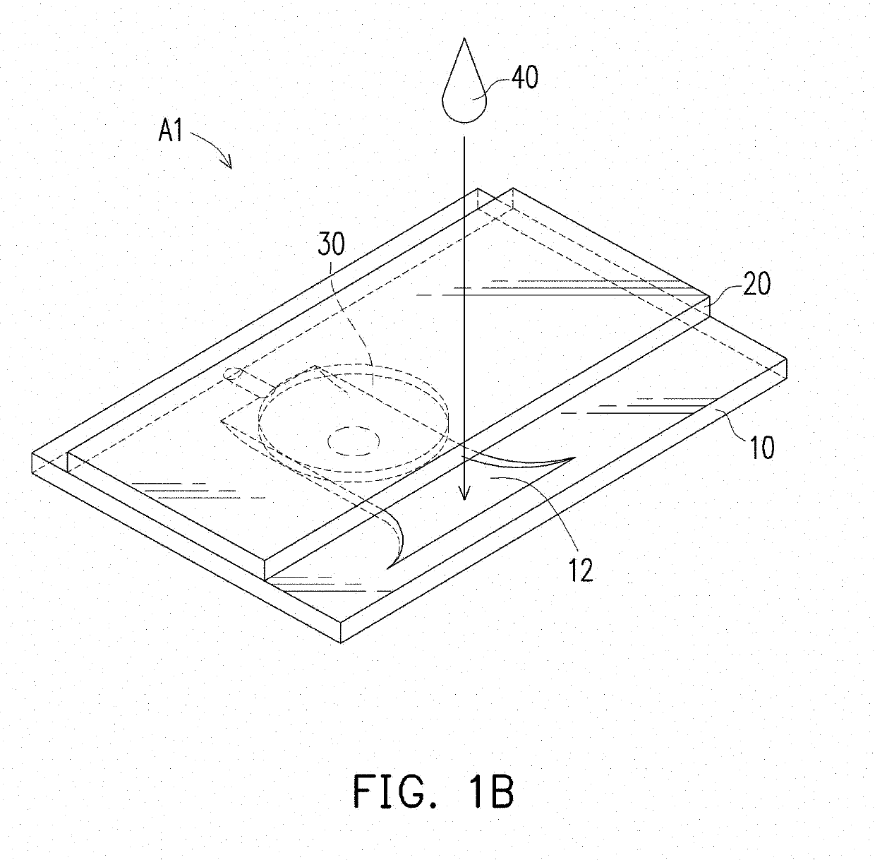
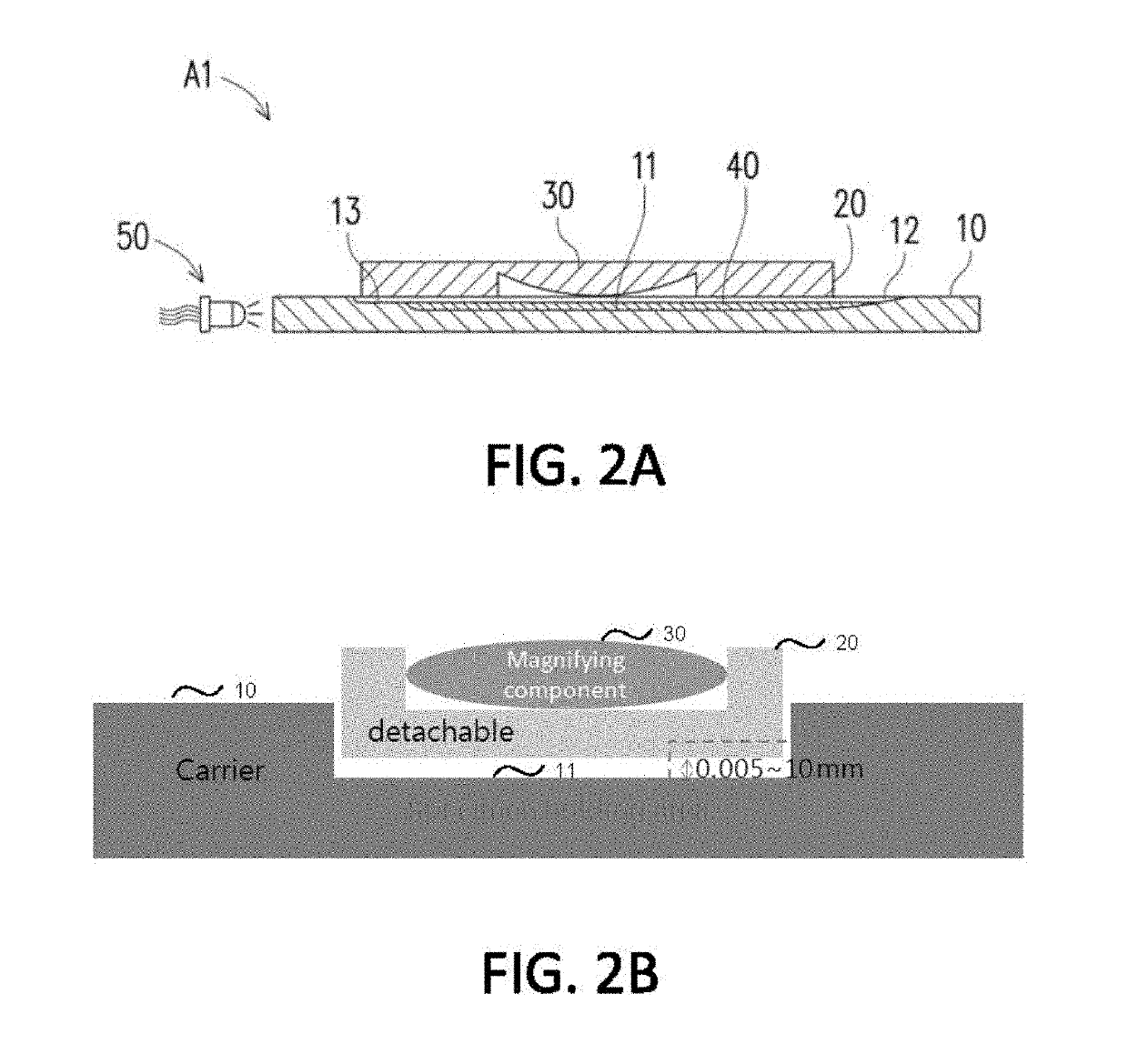
[0059]FIGS. 1A and 1B illustrate a testing equipment with magnifying function according to an embodiment of the invention. Embodiments disclosed herein are used for illustration purpose and should not be construed as required limitation to the invention. The testing equipment with magnifying function A1 includes: a carrier 10 having a specimen holding area 11 formed on top of the carrier 10, a cover 20 stacked on top of the carrier 10, and at least one magnifying part 30 (also referred to as magnifying component or magnifier) including a convex lens type surface formed on the cover 20.

[0060]The magnifying part 30 of the present embodiment includes a planar convex lens as illustrated in FIG. 1A. However, other type of magnifying lens, e.g., a dual-sided lenticular lens can be included as the magnifying part 30. The magnifying part 30 is disposed to be aligned with and to cover the specimen holding area 11 of the carrier 10. The magnifying part 30 may have various magnification ratios...


PUM

PropertyMeasurementUnit
focal lengthaaaaaaaaaa
distanceaaaaaaaaaa
distanceaaaaaaaaaa

Abstract

Embodiments disclose a device for testing biological specimen. The device includes a sample carrier and a detachable cover. The sample carrier includes a specimen holding area. The detachable cover is placed on top of the specimen holding area. The detachable cover includes a magnifying component configured to align with the specimen holding area. The focal length of the magnifying component is from 0.1 mm to 8.5 mm. The magnifying component has a linear magnification ratio of at least 1. Some embodiments further include a multi-camera configuration. These embodiments include a first camera module and a second camera module arranged to capture one or more images of the first holding area and the second holding area, respectively. The processor may perform different analytic processes on the captured images of different holding areas to determine an outcome with regard to the biological specimen.

Description

[0001]This application is a continuation-in-part of U.S. application Ser. No. 15 / 603,783, filed May 24, 2017, which is a continuation-in-part of U.S. application Ser. No. 15 / 345,061, filed Nov. 7, 2016; which is a continuation-in-part of U.S. application Ser. No. 15 / 152,470, filed May 11, 2016; the contents of the above applications are incorporated herein by reference in their entireties.FIELD OF THE INVENTION[0002]The invention relates to equipment for testing biological specimen, and relates particularly to testing equipment with a magnifying function or an analyte quantification function.BACKGROUND OF THE INVENTION[0003]Currently, testing of liquid contents, are typically consigned to professional testing authorities for performing testing using expensive microscope equipment with high magnification ratios. Since an individual does not have microscope equipment, the testing activity cannot be performed by the individual.[0004]However, in some testing categories nowadays testing ...

Claims


Application Information

Patent Timeline
Patent Type & Authority Patents(United States)
IPC IPC(8): G01N15/06G02B21/00G02B21/34G01N15/14G01N21/80A61B10/00
CPCG01N15/1429G01N15/1475G02B21/34G02B21/0008G01N21/80A61B10/0058G01N2015/144G01N2015/1006G01N15/1434G01N15/1433
Inventor HSU, CHENG-TENGHUANG, HSUAN-YUCHANG, CHIH-PINHUANG, KUANG-LICHI, YU-CHIAO
Owner BONRAYBIO
Learn More