Gas purge unit

a technology of gas purge unit and purge chamber, which is applied in the direction of cleaning hollow articles, cleaning process and apparatus, chemistry apparatus and process, etc., can solve the problem that conventional apparatuses cannot sufficiently reduce the rate of defective goods

Active Publication Date: 2019-04-30
TDK CORPARATION
View PDF15 Cites 1 Cited by
  • Summary
  • Abstract
  • Description
  • Claims
  • Application Information

AI Technical Summary

Benefits of technology

[0013]The gas purge unit according to the present embodiment discharges the gas to the outside through the discharge portion of the porous body. This can weaken speed and directivity of the discharged cleaning gas. Thus, a space where the speed of the cleaning gas is locally increased is hardly formed in the container, and the cleaning gas can be introduced into the transport container while preventing particle scattering.
[0015]Due to the operation of the shielding portion, the cleaning gas can be more efficiently introduced into the container, and a cleanliness in the container can be enhanced.
[0017]The porous body composing the discharge portion is cylindrical, and the cleaning gas is discharged from the entire cylindrical discharge portion. This can reduce dispersion of a discharge amount at every part of the discharge portion. This allows the gas purge unit with the discharge portion to efficiently introduce the cleaning gas into the entire container.
[0019]The porous body composing the discharge portion may be non-organic or organic material. When the discharge portion is made of the porous body of non-organic material, the housed object can be prevented from being adversely affected by mixture of organics in the cleaning gas.

Problems solved by technology

Thus, the conventional apparatuses cannot sufficiently decrease a rate of defective goods at the time of completion of elements in spite of introduction of the purge gas.

Method used


Image

  • Gas purge unit
  • Gas purge unit
  • Gas purge unit

Examples


Embodiment Construction

[0031]Hereinafter, the present invention will be explained with reference to an embodiment shown in the drawings.

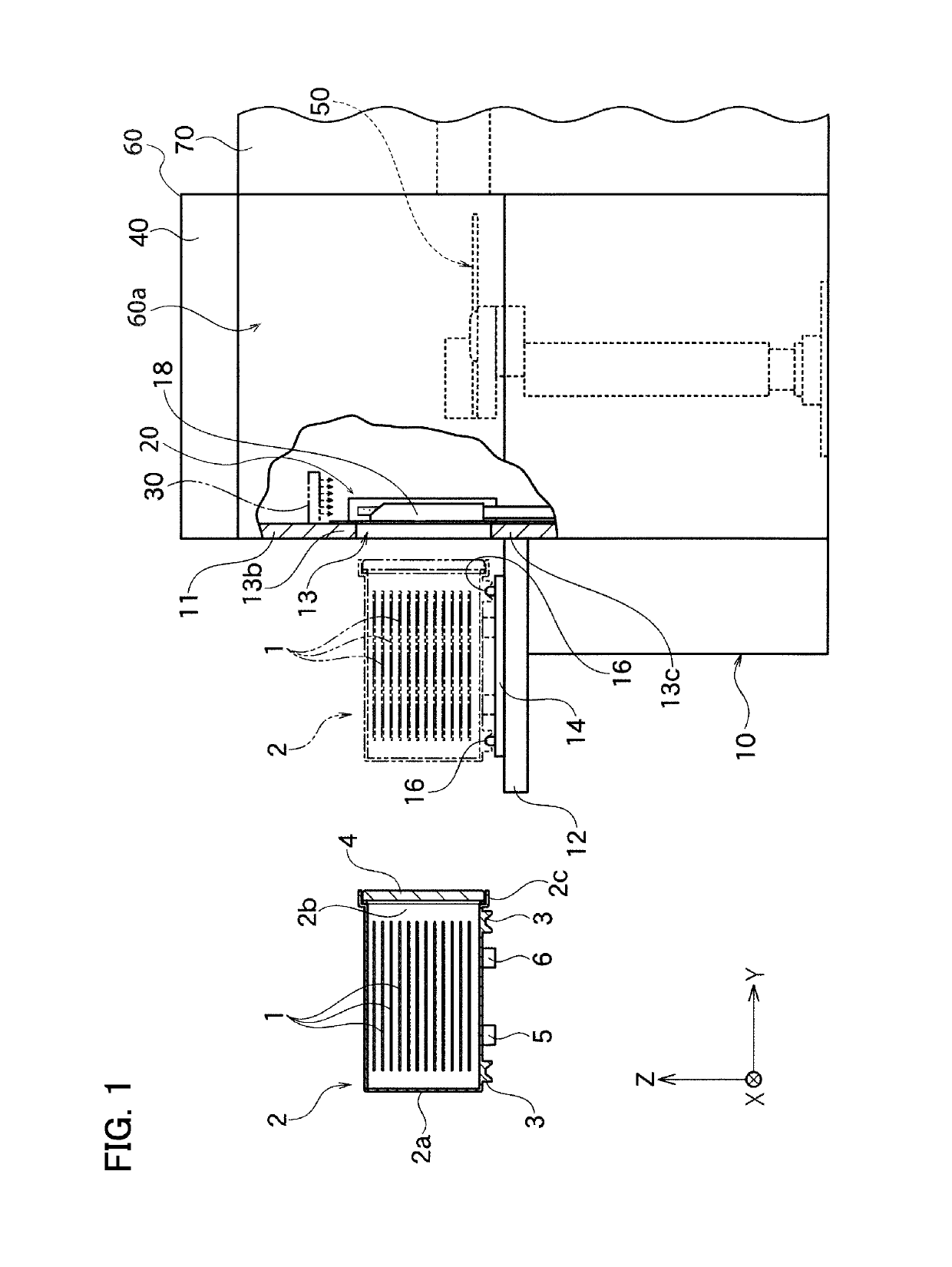
[0032]FIG. 1 is a partial cross-sectional schematic view of a load port apparatus 10 having gas purge units 20 according to one embodiment of the present invention. The load port apparatus 10 shown in FIG. 1 is connected to an intermediate chamber 60a of an EFEM body 60. In the embodiment mentioned below, the present invention will be explained with reference to the gas purge units 20 applied to the load port apparatus 10, but usage of the gas purge units 20 is not limited to the embodiment, and the gas purge units 20 can be applied to other apparatuses introducing a cleaning gas from a main opening for taking a housed object in and out.

[0033]The load port apparatus 10 is an interface apparatus for transporting wafers 1 housed in a sealed state in a sealed transport container 2 into the intermediate chamber 60a while maintaining a clean condition. One or plural processing...


PUM


Abstract

A gas purge unit introduces a cleaning gas into a container with a main opening there through for taking a housed object in and out. The gas purge unit includes a blowout member and a supply portion. The blowout member with a cylindrical shape has an elongated hollow extending in a longitudinal direction and a discharge portion of a porous body connecting between the elongated hollow and the outside to discharge the cleaning gas. The supply portion is connected to the elongated hollow through a connection hole formed at one end of the blowout member to supply the cleaning gas to the elongated hollow.

Description

BACKGROUND OF THE INVENTION[0001]1. Field of the Invention[0002]The present invention relates to a gas purge unit used for a manufacturing process of semiconductors, for example.[0003]2. Description of the Related Art[0004]In the manufacturing process of semiconductors, wafers housed in a wafer transfer container, called such as FOUP and pod, include one where high-density metal wirings or so are formed, for example. It may become impossible to obtain desired characteristics at the time of completion of elements simply because the wafer surface where such high-density metal wirings are formed is slightly oxidized during the process. To prevent foreign material deposition on the wafer surface and oxidation thereof during the process, the transport container is thus necessary to maintain its cleanliness at a high level while controlling oxygen concentration inside of the container.[0005]However, when the wafers in the transport container are brought to various processing apparatuses f...

Claims


Application Information

Patent Timeline
Patent Type & Authority Patents(United States)
IPC IPC(8): H01L21/673B05B1/34B05B1/00B08B5/02H01L21/67H01L21/677B08B9/093B08B9/00
CPCH01L21/67389H01L21/67772H01L21/67775B08B9/00
Inventor KUDO, TAKUYAMIYAJIMA, TOSHIHIKO
Owner TDK CORPARATION
Why Eureka
Try Eureka