
Controller for hybrid vehicle

a controller and hybrid technology, applied in the direction of engine-driven generators, transportation and packaging, transportation, etc., can solve the problems of driver discomfort and difficulty in maintaining the locked state of the sowc, and achieve the effect of reducing the likelihood, increasing the frequency, and preventing the driver from feeling discomfor

Inactive Publication Date: 2019-04-30
TOYOTA JIDOSHA KK
View PDF13 Cites 1 Cited by
  • Summary
  • Abstract
  • Description
  • Claims
  • Application Information

AI Technical Summary

Benefits of technology

The controller effectively maintains the locked state of the selectable one-way clutch, reducing driver discomfort and engagement delays by adjusting torque outputs to match the engine brake torque with the friction torque, ensuring consistent operation during fuel cut conditions.

Problems solved by technology

Accordingly, in the state in which the engine brake acts, it is difficult to maintain the locked state of the SOWC.
Accordingly, there is a possibility that a driver will feel discomfort based on an engagement delay or a busy feeling.

Method used


Image

  • Controller for hybrid vehicle
  • Controller for hybrid vehicle
  • Controller for hybrid vehicle

Examples


first embodiment

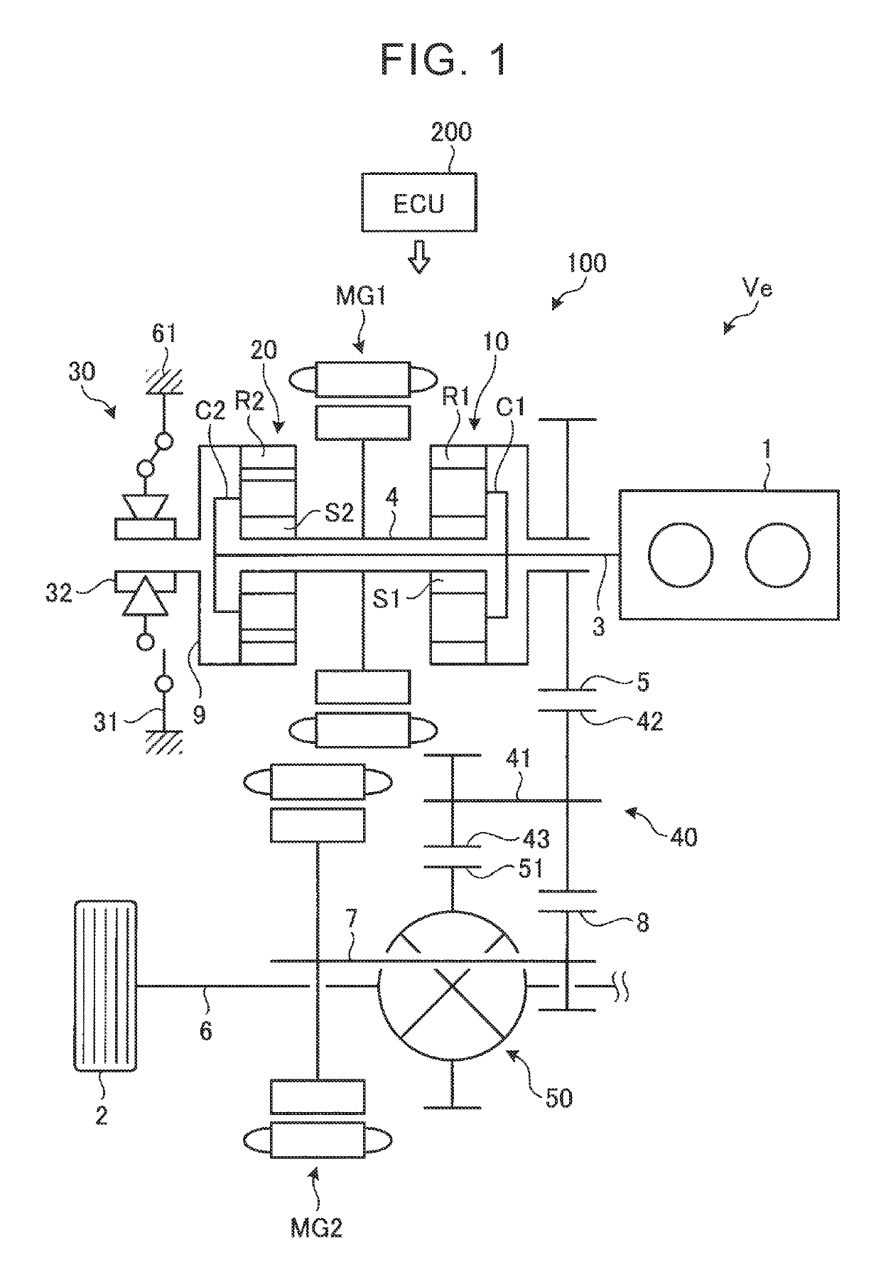
[0041]When the SOWC 30 is in the engaged state, the selector plate is opened and the strut rises by an operation of a spring, and the strut is inserted into a notch as an engagement recessed portion (both of which are not illustrated). Accordingly, in the SOWC 30, rotation in a negative direction as a predetermined one direction is permitted and rotation in a positive direction as the opposite direction is restricted. In the first embodiment, when the SOWC 30 is in the engaged state, rotation in the negative direction of the second ring gear R2 is permitted and rotation in the positive direction as the opposite direction is restricted. The positive direction is the same direction as the rotation direction of the crank shaft of the engine 1. The negative direction is the opposite direction to the positive direction. In this specification, in the SOWC 30 in the engaged state, a state in which rotation in the positive direction is restricted is referred to as a “locked state” and a sta...

second embodiment

[0079]FIG. 6 is a collinear diagram illustrating the MG1-locked driving mode in the hybrid vehicle according to the As illustrated in FIG. 6, in the MG1-locked driving mode, the overdrive state is achieved by restricting the rotation in the positive direction of the first sun gear S1, the rotation speed of the engine 1 increases, and the rotation of the engine 1 is output from the first ring gear R1 of the first planetary gear mechanism 10 to the counter gear mechanism 40.

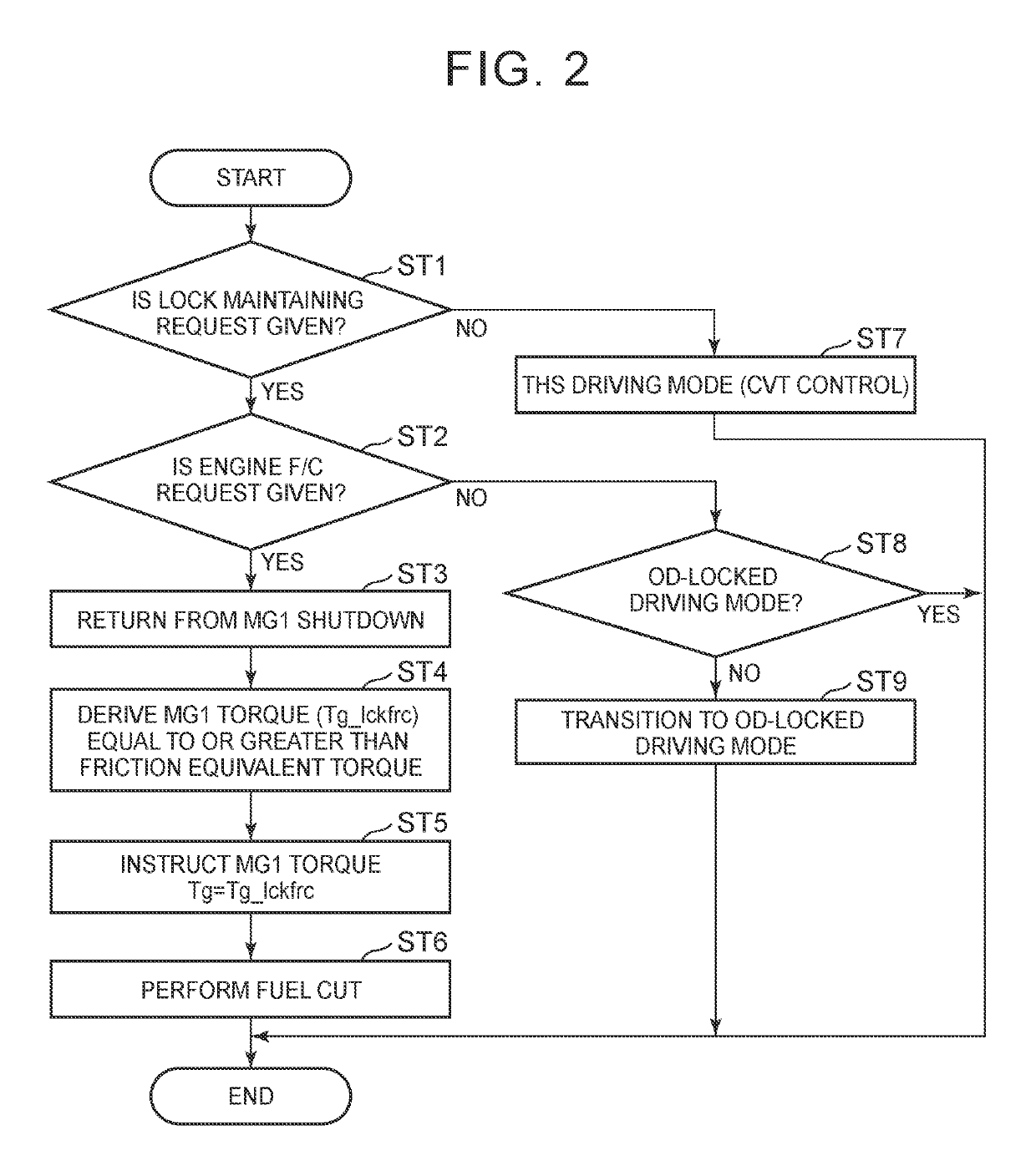
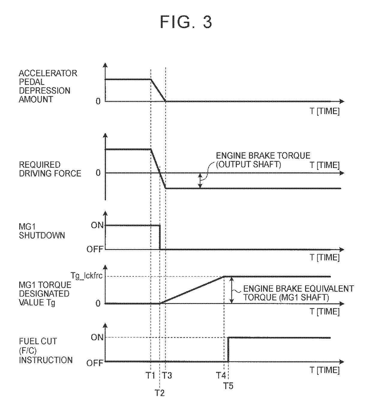
[0080]When fuel cut is instructed to the engine 1 in the MG1-locked driving mode, the ECU 200 controls the first motor MG1 such that a positive torque of an engine brake equivalent torque Tg_lckfrc is output. Accordingly, since the torque output from the first motor MG1 acts in the direction in which the rotation in the SOWC 30 is positive, the locked state of the SOWC 30 can be maintained even in a state in which a friction torque is generated.

[0081]When an engine brake torque output from the drive shafts 6 as an...


PUM


Abstract

A controller for a hybrid vehicle is provided. The hybrid vehicle includes an engine, a first electric motor, a second electric motor, a power split mechanism, and a selectable one-way clutch. The hybrid vehicle is configured to increase and transmit a rotation speed of the engine to an output shaft to drive the output shaft in an overdrive state when the selectable one-way clutch is in the engaged state. The controller includes an electronic control unit configured to control the first electric motor such that an engine brake equivalent torque with a magnitude sufficient to maintain the locked state of the selectable one-way clutch is output in a direction opposite to a direction of a negative torque which is generated in the engine when the hybrid vehicle travels in a state in which supply of fuel to the engine is stopped in the overdrive state.

Description

INCORPORATION BY REFERENCE[0001]The disclosure of Japanese Patent Application No. 2016-131773 filed on Jul. 1, 2016 including the specification, drawings and abstract is incorporated herein by reference in its entirety.BACKGROUND1. Technical Field[0002]The present disclosure relates to a controller for a hybrid vehicle.2. Description of Related Art[0003]In the related art, a configuration in which a planetary gear and a selectable one-way clutch (SOWC) are combined is known as a hybrid system for a vehicle. The SOWC is a clutch that can selectively switch between an engaged state in which rotation in only one predetermined direction is permitted and a disengaged state in which rotation in both directions is permitted. In the engaged state of the SOWC, the rotation in one direction in which rotation is permitted is in an unlocked state and the rotation in the opposite direction to the one direction in which rotation is not permitted is in a locked state.[0004]Japanese Patent Applicat...

Claims


Application Information

Patent Timeline
Patent Type & Authority Patents(United States)
IPC IPC(8): B60W30/18B60W10/08B60W20/15F16H3/72B60K6/445B60K6/36B60K6/383B60K6/442B60W10/02B60W20/40B60W30/188B60W10/06B60K6/365B60L50/16
CPCB60W10/08B60K6/442B60K6/445B60W10/02B60W20/15B60W20/40B60W30/188B60W30/18072F16H3/728B60K6/383Y02T10/7258B60K6/365B60W10/06B60W2510/0647F16H3/724Y02T10/6239Y02T10/62Y02T10/72
Inventor ITAGAKI, KENJIMAGARIDA, NAOFUMIKATO, KOICHI
Owner TOYOTA JIDOSHA KK
Learn More