
Coin sensor

a coin sensor and coin technology, applied in the field of coins, can solve the problems of inability to obtain parameters, and excessive complexity and space requirements, and achieve the effects of improving sensitivity and signal/noise ratio, precision and stability of measurements, and high reliability of coins

Active Publication Date: 2019-04-16
AZKOYEN
View PDF18 Cites 0 Cited by
  • Summary
  • Abstract
  • Description
  • Claims
  • Application Information

AI Technical Summary

Benefits of technology

This patent describes a method for identifying coins using inductive sensors. The measurements are obtained by measuring the changes in the inductors caused by the coin. The method includes measuring the mutual impedance between the inductors in three modes: in-phase, out-of-phase, and emitter-receiver. This allows for a highly accurate identification of coins, particularly for the purpose of rejecting counterfeit coins or interferences. The method also includes using a transimpedance amplifier for the receiver, which provides better sensitivity and smaller phase difference as compared to a differential amplifier. The adjustment in amplification can also be optimized for each mode by using the transimpedance amplifier.

Problems solved by technology

The described configuration has the drawback of using three inductors and also only operates in one mode, emitter-receiver, and is therefore not optimal, since it does not measure the impedances inherent to each of the inductors or for generating the in-phase and out-of-phase modes.
The analysis obtained is of the multi-frequency type by means of a single receiver and has the drawback that it only uses one operating mode and does not have individual inductor impedance measurements, which provide important information to achieve a good discrimination of genuine and counterfeit coins, either through direct information or by calculating the in-phase and out-of-phase modes.
In this sensor, the emitter-receiver mode is not used and, furthermore, the use of two pairs of sensors makes its complexity and required space excessive.
The proposed sensor only has one inductor, due to which it is not possible to obtain parameters related to mutual or emitter-receiver impedance.
Additionally, it has coin lift-off compensation (i.e. the change in the distance between the sensors and the coin along its travel path between the sensors, since the coin does not normally circulate to a constant position with respect thereto); however, all this is done at a single frequency, which is not ideal for a multi-layer coin sensor.

Method used


Image

  • Coin sensor
  • Coin sensor
  • Coin sensor

Examples


Embodiment Construction

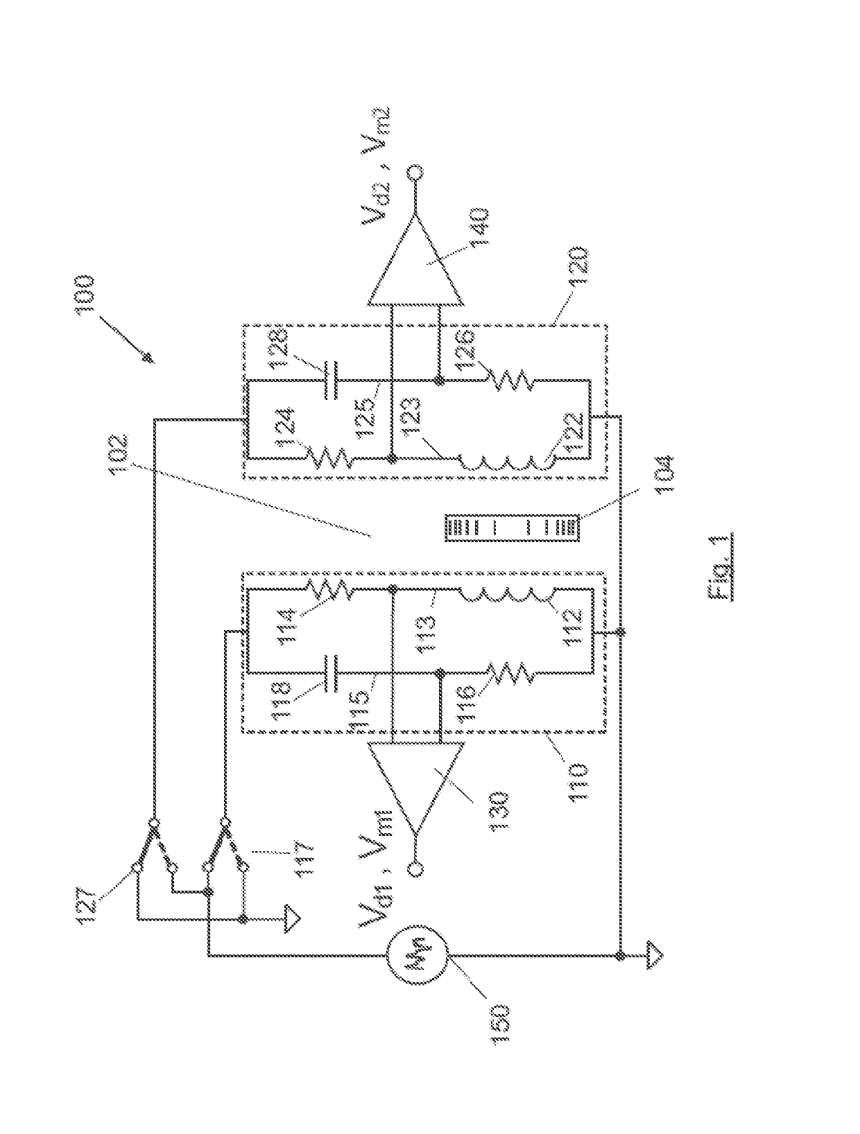
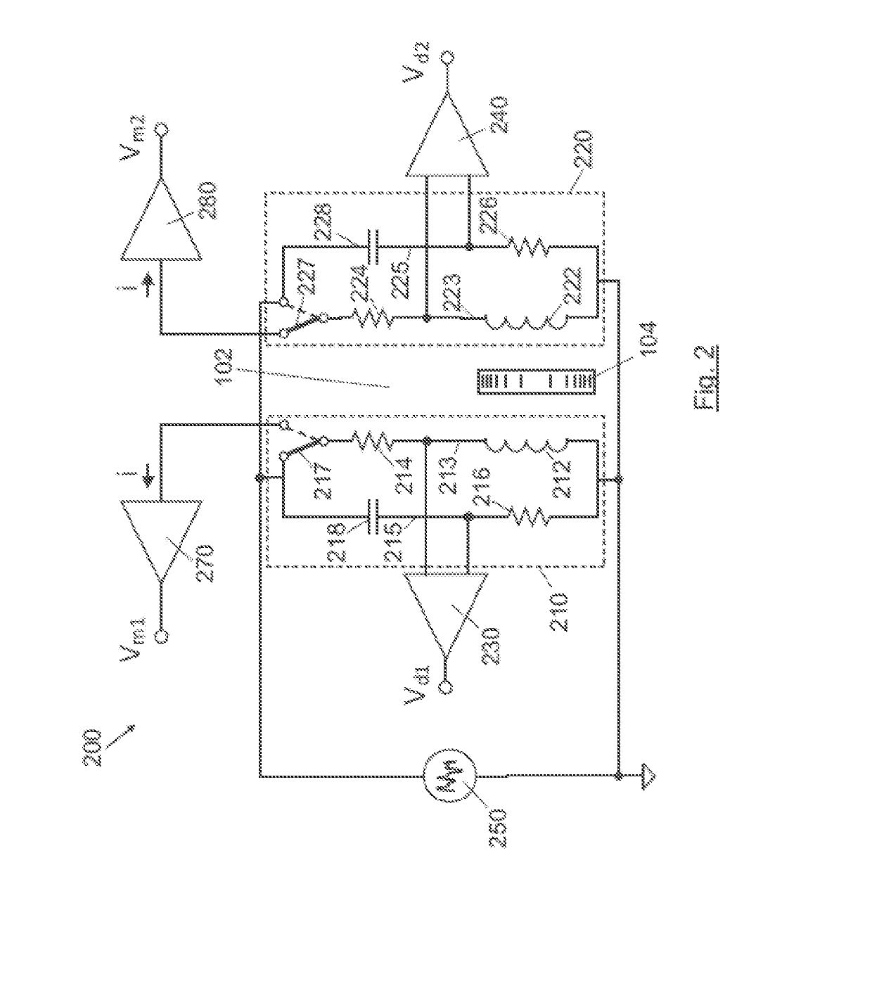
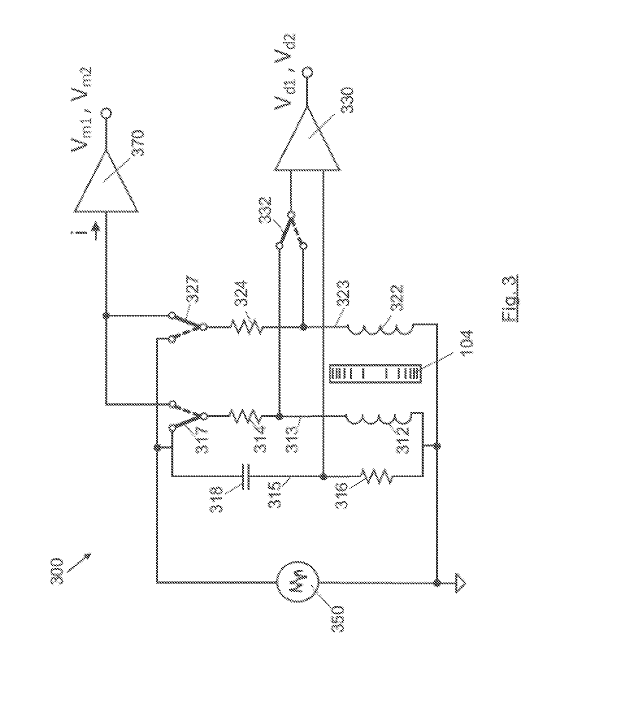
[0010]The object of the present invention is an electromagnetic coin sensor specially designed to measure multi-layer coins that resolves the aforementioned drawbacks. The sensor is composed of two inductors arranged facing each other between which the coin to be measured is made to pass. Each of the inductors forms part of an independent bridge (preferably a Maxwell bridge) when impedances corresponding to the sensor of the bridge being excited are measured.

[0011]The excitation of the bridge is performed by means of a pattern signal with spectral energy to the frequencies of interest. This pattern signal may be:[0012]A multi-tone signal, with components in the specific frequencies at which we wish to obtain information on coin passage. A multi-tone signal is composed of the sum of two or more pure sinusoidal waveforms, each with its amplitude, frequency and independent phases therebetween, but constant over time. In the embodiments detailed below, the signal used is composed of thr...


PUM

PropertyMeasurementUnit
frequenciesaaaaaaaaaa
voltageaaaaaaaaaa
capacitanceaaaaaaaaaa

Abstract

A coin sensor comprising a first inductive branch with a first inductor in series with a first resistor; a second inductive branch with a second inductor in series with a second resistor, wherein the first and second inductors are arranged facing each other on both sides of a passage channel of coins to be discriminated; at least one capacitive branch with a condenser and a resistor in series; an excitation circuit with a generator and at least one pair of switches, configured to alternately feed the first inductive branch and the second inductive branch with a pattern signal with spectral energy in two or more frequencies, such that the branch of the inductor excited at any given time is arranged in a bridge configuration with at least one capacitive branch; at least one differential amplifier configured to alternately measure the voltage between the exit nodes of the excited bridge.

Description

CROSS REFERENCE TO RELATED APPLICATION[0001]This application claims priority of European Application No. 17382452.5 filed Jul. 11, 2017, application which is incorporated herein by reference.FIELD OF THE INVENTION[0002]The present invention relates to a device and the corresponding method applicable to the characterisation and recognition of coins, especially of the multi-layer type, that uses one or more pairs of inductors between which the coins circulate.BACKGROUND OF THE INVENTION[0003]There are a multitude of devices and methods for measuring characteristics of coins and for identifying or recognising them with respect to legal tender which use inductive, capacitive, optical, electromagnetic, acoustic or piezoelectric sensors, aimed at obtaining the physical characteristics of legal tender, such as dimensional, mechanical and especially electrical and magnetic characteristics.[0004]In the case of magnetic sensors, it is normal to use pairs of inductors arranged facing each othe...

Claims


Application Information

Patent Timeline
Patent Type & Authority Patents(United States)
IPC IPC(8): G01N27/72G07D5/02G07D5/08G01B7/06
CPCG07D5/08G07D5/02G01B7/10G01B7/08
Inventor OSA LABRADOR, JUAN IGNACIOORDOYO CASADO, CRISTIANQUINTILLA QUINTILLA, LORENZOPINA INSAUSTI, JOSE LUISCALLEJA LAFUENTE, MIGUEL ANGELARIZTI URQUIJO, FERNANDO JOSESEVILLANO BERASATEGUI, JUAN FRANCISCO
Owner AZKOYEN
Learn More