
Method for manufacturing rotors

a manufacturing method and rotor technology, applied in the field of manufacturing rotors, can solve the problems of reducing operational efficiency, reducing unable to easily separate electric rotating machinery from people's daily life, so as to achieve the effect of improving the yield of rotors, reducing the cost of manufacturing, and improving the structural performance of rotors

Active Publication Date: 2019-03-19
TECO ELECTRIC AND MACHINERY
View PDF2 Cites 0 Cited by
  • Summary
  • Abstract
  • Description
  • Claims
  • Application Information

AI Technical Summary

Benefits of technology

The present invention improves the structure of a rotor by adding a beetling process, which increases the yield of the rotor structure. The use of different materials, such as copper and aluminum, in the metal bar and metal slurry allows for the advantages of each material to be preserved, resulting in better performance of the motor. Further, by providing notched terminal portions on the metal bar, the possibility of looseness between different materials is reduced, ensuring production reliability.

Problems solved by technology

Thus, the electric rotating machinery can't be easily separated from people's daily life.
However, shortcomings in heavier weight and higher cost would be yet to be resolved.
However, the operational efficiency is downgraded.
In the aluminum rotor, the rotor made of the cast aluminum is implanted with aluminum bars, through which, though the coefficient of resistance is high, the lower operational efficiency is yet to be improved.

Method used


Image

  • Method for manufacturing rotors
  • Method for manufacturing rotors
  • Method for manufacturing rotors

Examples


Embodiment Construction

[0025]The invention disclosed herein is directed to a method for manufacturing rotors. In the following description, numerous details are set forth in order to provide a thorough understanding of the present invention. It will be appreciated by one skilled in the art that variations of these specific details are possible while still achieving the results of the present invention. In other instance, well-known components are not described in detail in order not to unnecessarily obscure the present invention.

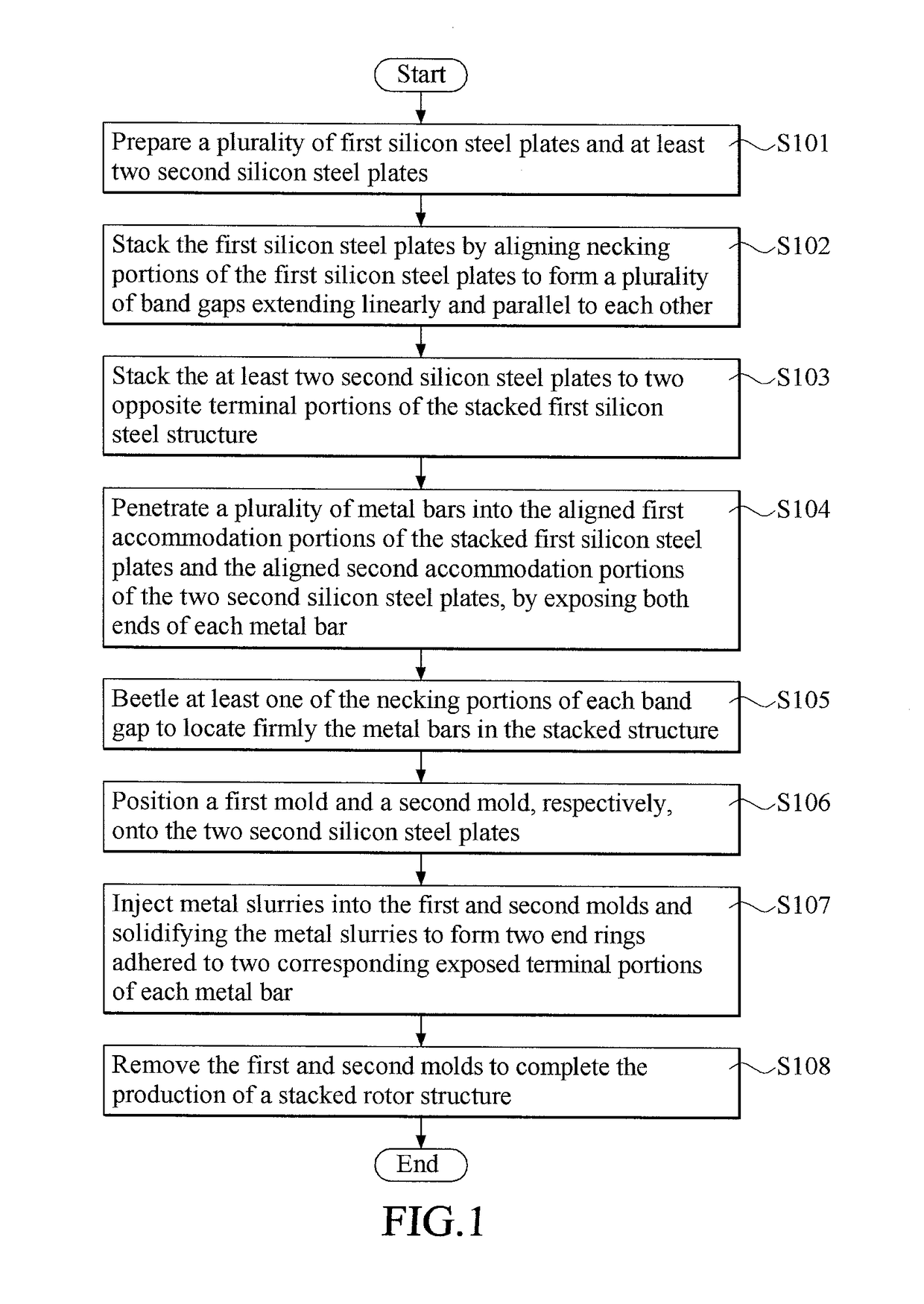
[0026]Refer to FIG. 1 to FIG. 8; where FIG. 1 is a flowchart of a preferred embodiment of the method for manufacturing rotors in accordance with the present invention, FIG. 2 is a schematic perspective view of a first silicon steel plate for the embodiment of FIG. 1, FIG. 3 is a schematic perspective view of a second silicon steel plate for the embodiment of FIG. 1, FIG. 4 is a schematic lateral side view of a metal bar for the embodiment of FIG. 1, FIG. 5 is a schematic perspecti...


PUM

PropertyMeasurementUnit
band gapsaaaaaaaaaa
weightaaaaaaaaaa
coefficient of resistanceaaaaaaaaaa

Abstract

A method includes steps of: preparing first and second plates, each first plate having surrounding apertures, each aperture including a first accommodation portion and an outer necking portion, each second plate having surrounding accommodation portions; stacking the first plates by aligning necking portions to form band gaps extending linearly and parallel to each other; stacking two second plates to two opposing terminal portions of the stacked first plates; penetrating metal bars into the aligned first and second accommodation portions by exposing both ends of each metal bar; beetling the necking portions at each band gap so as to locate firmly the corresponding metal bar; positioning a first mold and a second mold to clamp the stacked plate structure; injecting metal slurries into the first and second molds and then solidifying the metal slurries to form two end rings; and, removing the first and second molds to complete a rotor structure.

Description

[0001]This application claims the benefit of Taiwan Patent Application Serial No. 105124772, filed Aug. 4, 2016, the subject matter of which is incorporated herein by reference.BACKGROUND OF INVENTION1. Field of the Invention[0002]The invention relates to a method for manufacturing rotors, and more particularly to the manufacturing method of rotors that applies a beetling process upon a necking portion of a stacked silicon steel plate with an implanted metal bar.2. Description of the Prior Art[0003]In the art, the mainstream of electric rotating machinery is the electric induction apparatus such as the motor. Since its excellent applicability and sturdiness, the electric induction apparatus is continuously and widely adopted. No matter in the manufacturing or livelihood industry, the electric induction apparatus always plays an important or key role. Thus, the electric rotating machinery can't be easily separated from people's daily life.[0004]In particular, the slot shape of the ro...

Claims


Application Information

Patent Timeline
Patent Type & Authority Patents(United States)
IPC IPC(8): H02K15/02H02K15/12B23P15/00H02K15/00B23P11/00
CPCH02K15/12B23P15/00H02K15/02H02K15/024H02K15/0012B23P11/005
Inventor HSU, MENG-YUANHUNG, LIAN-SHINSHIH, CHENG-HSUANWANG, CHI-HSINWANG, SHENG-YI
Owner TECO ELECTRIC AND MACHINERY
Learn More