
Device and method for controlling deposit formation

a technology of deposit formation and control device, which is applied in the direction of water treatment parameter control, specific water treatment objectives, water/sludge/sewage treatment, etc., can solve the problems of liquid that is processed under such harsh process conditions, and achieve the effect of promoting deposit formation, reducing specific fouling detected, and substantially improving deposit control

Active Publication Date: 2019-03-19
SOLENIS TECH CAYMAN
View PDF17 Cites 0 Cited by
  • Summary
  • Abstract
  • Description
  • Claims
  • Application Information

AI Technical Summary

Benefits of technology

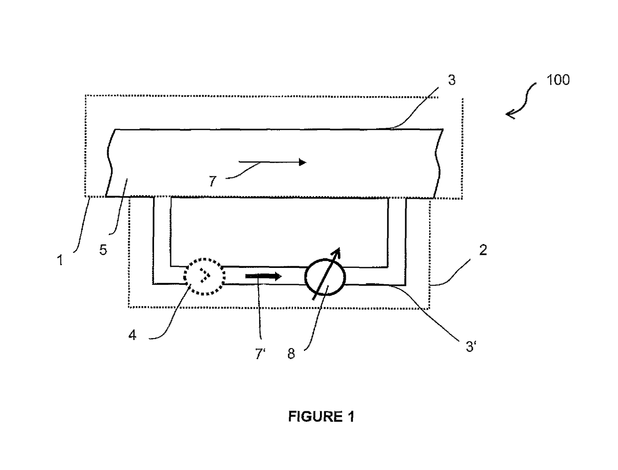
[0013]It is herewith advantageously possible to use the subsystem as a watchdog or as an early warning system, because it has been surprisingly found that artificial process conditions can be established that promote deposit formation, i.e. that are harsher process conditions with respect to deposit formation. Thus, the liquid that is processed under such harsher process conditions tends to form deposits, in particular scaling, inside the subsystem ahead of the recirculating liquid that is processed under the current operational conditions of the liquid bearing system inside the main system. Such a method may ensure that a proper countermeasure is initiated before deposit formation inside the main system of the liquid bearing system even starts. In particular, the main system and the subsystem are configured such that the liquid has access to both the main system and the subsystem. As a result the concentration of a treatment chemical inside the subsystem is the same as the concentration of the treatment chemical inside the main system advantageously. The treatment chemical may be configured such that the treatment chemical comprises antideposit components. Moreover it is provided that the liquid is recirculated inside the liquid bearing system. Preferably the liquid comprises water and the liquid bearing system comprises a cooling tower or a tank. Deposits are for example scale, fouling and / or corrosion products such as iron oxides. In particular the treatment chemical comprises antisling products, antifouling products and / or anticorrosion products. Furthermore it is provided that the countermeasure is adapted to the kind of deposit. As a consequence the composition of the treatment chemical may be adapted to the kind of deposit. For example the treatment chemical comprises an antifouling component that reduces the specific fouling detected inside the subsystem. It is also thinkable that the chemical treatment is fed to the liquid bearing system at a feeding rate, wherein the feeding rate depends on the type of the deposit. In particular it is thinkable that the treatment chemical is fed to the liquid bearing system in a continuous or pulsed form. Moreover it is provided that treatment chemicals are fed to the liquid bearing system all the time, wherein the composition of the treatment chemical is changed as soon deposit formation is detected inside the subsystem. Further it has been surprisingly found that the artificial process conditions can be adjusted over a broad range so that different degrees of harshness are possible. In consequence, a buffer between the harsher conditions in the bypass and the current conditions in the operational water bearing system can be freely adjusted to allow for a comparatively early or for a comparatively late initiation of counter measure, respectively. It is also conceivable that the deposit formation is derived from detecting a key operation indicator such as pH value, electrical conductivity and the like. Furthermore it is provided that the pipes of the main system and the subsystem are made from the same material.
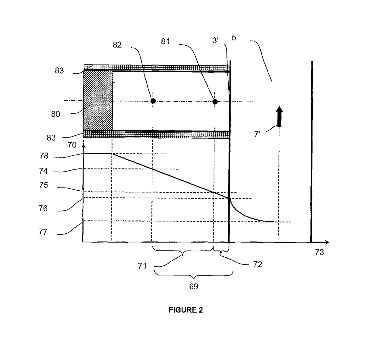
[0015]In another embodiment it is provided that the subsystem is a bypass. It has been surprisingly found that the monitoring of key performance indicators can advantageously be performed in a bypass wherein artificial process conditions that promote deposit formation are set inside the bypass. Once a significant change of key performance indicators is detected under the artificial conditions within the bypass, e.g. the beginning of scaling, appropriate countermeasures may be initiated, e.g. by increasing the dosage of anti-scaling additive. As the environment in the bypass is more favorable for deposit formation than in the main system, scaling has not yet begun in the main system and can thus be effectively prevented. This has particularly advantageous with respect to scaling which can usually not be removed by means of anti-scaling additives once it has been deposited on a surface. Preferably, the condition of the liquid, in particular of recirculating water, in the bypass differs from the condition of the liquid in the main system. Preferably, the temperature and / or the flow velocity of the recirculating water in the bypass is / are higher than that of the recirculating water in the main system.
[0016]In another embodiment of the present invention it is provided at least one property of the liquid inside the subsystem is manipulated by a manipulation device. Preferably the liquid inside the subsystem and the liquid in the main system have only one non-equivalent property. As a consequence the subsystem represents the main system as closely as possible advantageously. Furthermore, it has been surprisingly found that artificial process conditions can be established without substantially altering the thermal conditions of the system. In particular, it has been surprisingly found that the temperature of the recirculating water in the bypass does not need to be changed compared to the temperature of the recirculating water in the operational water bearing system.
[0032]In another embodiment of the present invention it is provided that the subsystem comprises a heater. Such a heater may heat the liquid in the subsystem. As a result it is advantageously possible to simulate the thermodynamic condition of a part of the main system being far away from the subsystem, wherein the liquid inside the part of the main system has a higher temperature than the liquid inside an unheated subsystem. Such parts of the main system are for example parts of the main system that are responsible for a heat exchange. The temperature of the part of the main system being far away from the subsystem favors deposit formation inside the part of the main system compared to those parts of the main system having a lower temperature. Equalizing the thermodynamic conditions of the liquid inside the subsystem and inside the part of the main system being far away from the substrate may guarantee that the subsystem even operates as an early warning system for parts of the main system that are usually favored for deposit formation.
[0037]It is herewith advantageously possible to detect and / or identify deposit inside the subsystem and timely react by initiating countermeasures in order to avoid deposit formation inside the main system.
[0039]It is herewith advantageously possible to mount the subsystem to the liquid bearing system easily. As a result the mounted upgrade may identify timely deposit formation, in particular scaling, inside the subsystem and therefore proper countermeasures may be started in order to avoid deposit formation inside the liquid bearing system.

Problems solved by technology

Thus, the liquid that is processed under such harsher process conditions tends to form deposits, in particular scaling, inside the subsystem ahead of the recirculating liquid that is processed under the current operational conditions of the liquid bearing system inside the main system.

Method used


Image

  • Device and method for controlling deposit formation
  • Device and method for controlling deposit formation
  • Device and method for controlling deposit formation

Examples


Embodiment Construction

[0045]The present invention will be descripted with respect to particular embodiments and with the reference to certain drawings but the invention is not limited thereto but only by the claims. The drawings described are only schematic and are non-limiting. In the drawings, the size of some elements may be exaggerated and not drawn on scale for illustrative purposes.

[0046]Where an indefinite or definite article is used when referring to a singular noun, e. G. “a”, “an”, “the”, this includes a plurals of the noun unless something else is specifically stated.

[0047]Furthermore, the terms first, second, third and the like in the description and in the claims are used to distinguishing between similar elements and not necessarily for describing a sequential or chronological order. It is to be understood that the terms so used are interchangeable under appropriate circumstances and that the embodiments of the invention described herein are capable of operation in other sequences than desc...


PUM

PropertyMeasurementUnit
Reynolds numberaaaaaaaaaa
flow velocityaaaaaaaaaa

Abstract

The invention suggests a method for controlling the deposit formation in a main system of a liquid bearing system, wherein a liquid is transported inside the liquid bearing system, wherein the liquid bearing system comprises a main system and a subsystem, wherein the subsystem is configured such that a tendency of deposit formation is promoted more inside the subsystem than inside the main system.

Description

FIELD OF THE INVENTION[0001]The invention relates to the deposit control in water bearing systems, particularly in open recirculating cooling water systems.BACKGROUND[0002]Open recirculating cooling water systems are widely used processes for rejection of waste heat from a variety of industrial processes. Such systems are open as water e.g. evaporates at the cooling tower. In addition, controlled removal of recirculating water is necessary to limit the accumulation of dissolved species that cause corrosion, scaling and fouling. The effluent water is removed with the so-called “blowdown stream”.[0003]Various additives are on the market that can be added to the recirculating water in order to specifically avoid corrosion, scaling or fouling. These additives are normally fed at a feeding rate needed to maintain a relatively constant concentration in the recirculating water. The feeding rate is typically controlled to replace the amount of the additives that are consumed within the reci...

Claims


Application Information

Patent Timeline
Patent Type & Authority Patents(United States)
IPC IPC(8): C02F1/00C02F5/02G01N29/024G01B17/02C02F103/02
CPCC02F5/02C02F1/008G01N29/024C02F2103/023C02F2209/001C02F2209/02G01N2291/044C02F2209/44C02F2303/22G01B17/025G01N2291/022G01N2291/0258G01N2291/02854C02F2209/40C02F1/36
Inventor FLOCKEN, CHRISTIANSEIDA, FRANK
Owner SOLENIS TECH CAYMAN
Learn More