Pneumatic brake release apparatus used on elevator traction machine

a technology of pneumatic brake and elevator, which is applied in the direction of elevator, transportation and packaging, hoisting equipment, etc., can solve the problems of urgent energy-saving work of elevator, waste of electric energy for useless work, and difficulty in eliminating noise, and achieves no noise, no noise, and greatly increased electric energy utilization rate

Active Publication Date: 2019-03-12
BEIJING SUNWA ELEVATOR
View PDF10 Cites 0 Cited by
  • Summary
  • Abstract
  • Description
  • Claims
  • Application Information

AI Technical Summary

Benefits of technology

[0005]In view of this, the main objective of the utility model is to provide a pneumatic brake release apparatus used on an elevator tractor, which aims at solving the problems that the existing electromagnetic locking brake apparatus is vast in electricity consumption, difficult to eliminate noise and the like. By means of the technical solution, the utilization rate of electric energy is greatly increased, no noise is generated when the elevator is operated, the safety is high and the structure is simple, thereby compensating for the defects in the prior art.
[0008]By adopting the above-mentioned technical solution, the utility model has the beneficial effects that: in the pneumatic brake release apparatus used on the elevator traction machine, by means of the technical solution, the air films in the air cabin are pushed by using compressed air to drive the push rod to transfer a thrust force; the locking arms are unfolded; the locking arms are ensured to be unfolded for a long time in the case of maintaining the air pressure; one of the air control apparatuses is opened so as to perform an effect of preventing accidental release of the brake; in the case of sudden damage or failure of the brake springs, the locking brake and the brake release can be realized in a pneumatic way, so that the problems in the prior art that a great amount of electric energy is consumed, and the noise is difficult to eliminate can be solved; no noise is generated during operation; the safety is high; the structure is simple; and the manufacturing cost is greatly reduced.

Problems solved by technology

With the intensive development of cities and the emergence of a great number of urban high-rise buildings, an elevator as a vertically running transportation means in the high-rise buildings has already been inseparable to daily life of people.
However, since a brake device can keep a release state only when being continuously energized if the vertically-running elevator runs normally, the coils are liable to heat, and a great amount of useless-work electric energy is wasted; the elevator as one of the largest “power consumption tigers” of modern buildings consumes a great amount of energy, and people at all sectors of society have weak consciousness of the energy conservation of the elevator.
Therefore, the energy-saving work of the elevator is urgent.

Method used


Image

  • Pneumatic brake release apparatus used on elevator traction machine

Examples


Embodiment Construction

[0011]Concrete embodiments in the utility model are further described below in detail in combination with drawings.

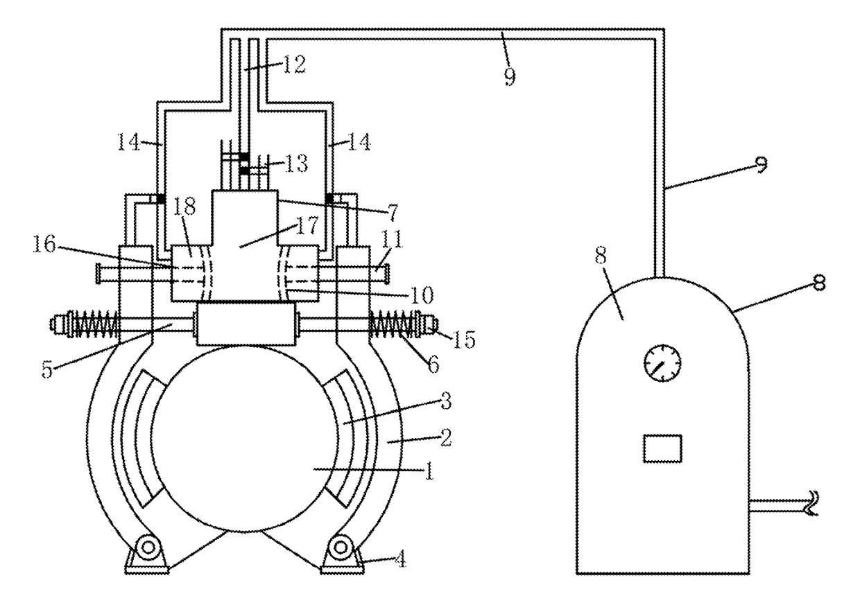
[0012]As shown in FIG. 1, a pneumatic brake release apparatus used on an elevator traction machine in the utility model includes locking arms 2 arranged at two sides of a brake wheel 1; the locking arms 2 are respectively provided with a locking block 3 abutted against the brake wheel 1; one end of each locking arm 2 is respectively hinged on a base 4; a connecting rod 5 is fixed on the bases 4; brake springs 6 are respectively sleeved over the connecting rod 5; one end of each brake spring 6 is abutted against one end of the connecting rod 5, and the other end of each brake spring 6 is abutted against the other end of the locking arm 2; and the pneumatic brake release apparatus also includes an air cabin 7, an air storage tank 8, air delivery pipes 9, air films 10, a push rod 11 and air control apparatuses; the air cabin 7 is arranged in the middle of the two locking a...


PUM


Abstract

A pneumatic brake release apparatus used on an elevator traction machine, includes an air cabin, an air storage tank, air delivery pipes, air films, a push rod and air control apparatuses. The air films are arranged at two sides in the air cabin, one end of the push rod is connected to the air films, the other end of the push rod penetrates through the outer wall of the air cabin and is connected with the upper end of a locking arm, an intermediate air cabin of the air cabin is provided with an intermediate air inlet end and an intermediate air outlet end, a film-anterior air cabin of the air cabin is provided with a film-anterior air inlet end, the intermediate air inlet end and the film-anterior air inlet end of the air cabin are respectively connected with the air storage tank by virtue of the air delivery pipes, and the intermediate air outlet end is directly communicated with the atmosphere.

Description

CROSS-REFERENCE TO RELATED APPLICATIONS[0001]This application is a continuation of International Patent Application No. PCT / CN2016 / 070262 with a filing date of Jan. 6, 2016, designating the United States, now pending, and further claims priority to Chinese Patent Application No. 201510017904.X with a filing date of Jan. 14, 2015, designating the United States, now pending. The content of the aforementioned applications, including any intervening amendments thereto, are incorporated herein by reference.TECHNICAL FIELD[0002]The utility model relates to a pneumatic brake release apparatus of an elevating device, and in particular relates to a pneumatic brake release apparatus used on an elevator traction machine.BACKGROUND OF THE PRESENT INVENTION[0003]With the intensive development of cities and the emergence of a great number of urban high-rise buildings, an elevator as a vertically running transportation means in the high-rise buildings has already been inseparable to daily life of ...

Claims


Application Information

Patent Timeline
Patent Type & Authority Patents(United States)
IPC IPC(8): B66B1/32F16D65/06F16D65/18F16D59/02F16D49/16B66D5/26B66B1/36F16D65/22F16D121/10F16D121/14F16D127/02F16D129/02
CPCF16D59/02B66B1/32B66B1/36B66D5/26F16D49/16F16D65/18F16D65/22F16D65/06F16D2129/02F16D2121/10F16D2121/14F16D2127/02
Inventor LUO, HAIMIN
Owner BEIJING SUNWA ELEVATOR
Why Eureka
Try Eureka