Eureka AIR delivers breakthrough ideas for toughest innovation challenges, trusted by R&D personnel around the world.

Actively controllable heart valve implant and method of controlling same

a heart valve and active control technology, applied in the field of heart valve implants, can solve the problems of affecting the function of the valve, the size of the valve opening of the implant may be too large for the patient, and is not desirable, so as to improve the function and durability of the valve, improve the functionality of the valve, and prolong the life.

Active Publication Date: 2019-03-12
EDWARDS LIFESCI CARDIAQ
View PDF648 Cites 24 Cited by
  • Summary
  • Abstract
  • Description
  • Claims
  • Application Information

AI Technical Summary

Benefits of technology

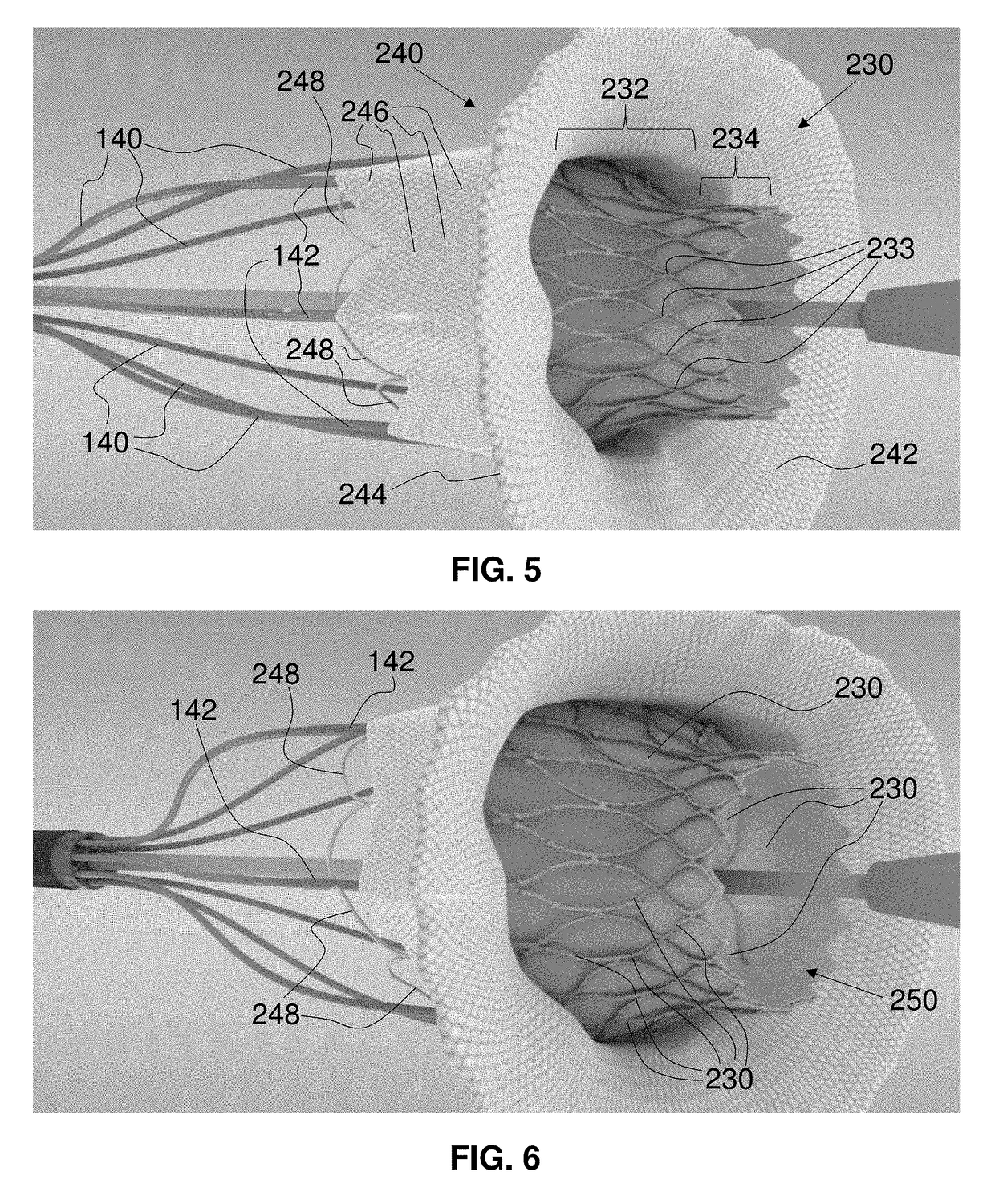
[0018]A further advantage of some of the embodiments of herein-described mitral valve implants relates to the size of the valve portion when the implant is secured in the native annulus. The native annulus of mitral valves are substantially D-shaped. One characteristic of a diseased mitral valve is that the annulus stretches outwardly, leaving the leaflets of the mitral valve unable to coapt and, thereby, impairing the functionality of the valve. In what is referred to as Mitral Valve Prolapse, one or both of the valve flaps are enlarged and do not close in an even manner. With improper closure, blood could flow backwards into the left atrium, referred to as Mitral Valve Regurgitation. With a stretching of the mitral valve annulus, even if a prior art implant is able to be secured therein, the size of that implant's valve opening may be too large for the patient. Some of the embodiments of the mitral valve implant herein provide a valve opening sized for optimal flow irrespective of the size of the diseased mitral valve annulus. These embodiments provide a fixed-sized valve opening contained within a variable outer annular skirt, the combined structures of the variably sized outer skirt and the fixed-sized valve being referred to herein as a trampoline valve. These exemplary implants, therefore, provide an ideal amount of flow through the valve of the implant in spite of the enlarged native mitral valve annulus. This means that, regardless of the final D-shaped diameter of the implanted stent lattice, the trampoline valve will have its own fixed maximum circular diameter, which improves valve function and durability. This feature allows a standard-sized valve to cover a large patient population with mitral valves of various sizes. The skirt can optionally have a downstream flair that creates a back seal when high pressure of ventricle contraction is imparted.

Problems solved by technology

Such a result is not desirable for many reasons, e.g., leakage, movement, and / or embolization.
One characteristic of a diseased mitral valve is that the annulus stretches outwardly, leaving the leaflets of the mitral valve unable to coapt and, thereby, impairing the functionality of the valve.
With a stretching of the mitral valve annulus, even if a prior art implant is able to be secured therein, the size of that implant's valve opening may be too large for the patient.

Method used


Image

  • Actively controllable heart valve implant and method of controlling same
  • Actively controllable heart valve implant and method of controlling same
  • Actively controllable heart valve implant and method of controlling same

Examples


Embodiment Construction

[0147]As required, detailed embodiments of the systems, apparatuses, and methods are disclosed herein; however, it is to be understood that the disclosed embodiments are merely exemplary of the systems, apparatuses, and methods, which can be embodied in various forms. Therefore, specific structural and functional details disclosed herein are optional and not to be interpreted as limiting, but merely as a basis for the claims and as a representative basis for teaching one skilled in the art to variously employ the systems, apparatuses, and methods in virtually any appropriately detailed structure. Further, the terms and phrases used herein are not intended to be limiting; but rather, to provide an understandable description of the systems, apparatuses, and methods. While the specification concludes with claims defining the features of the systems, apparatuses, and methods that are regarded as novel, it is believed that the systems, apparatuses, and methods will be better understood f...


PUM


Abstract

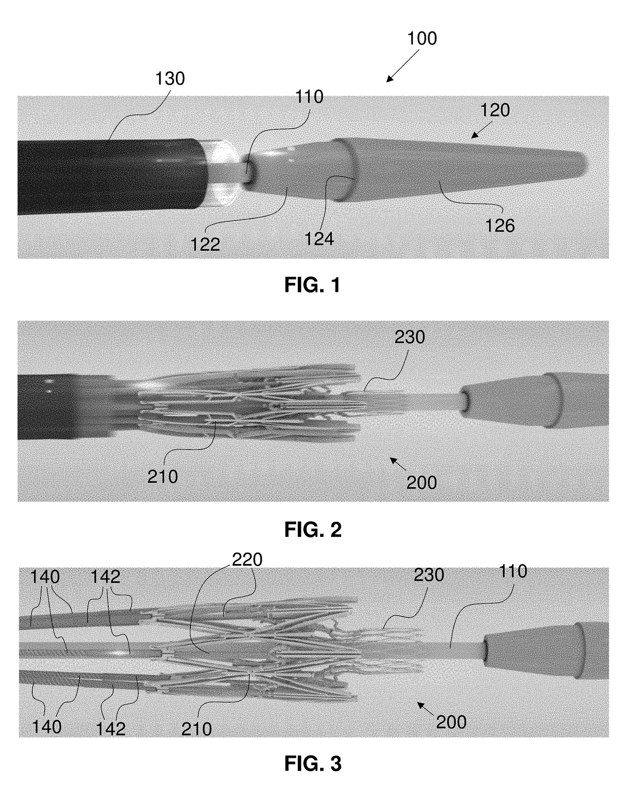
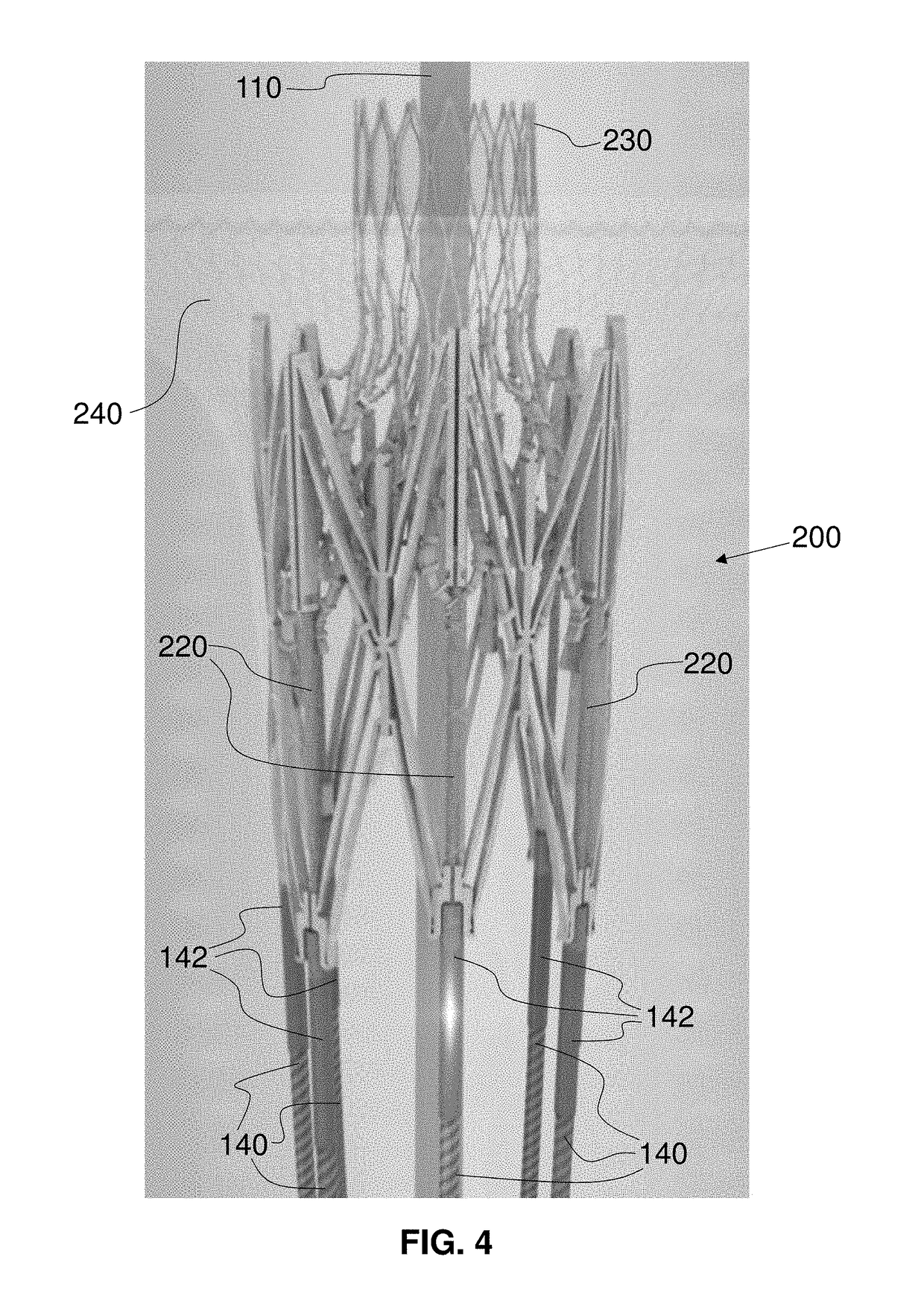
A mitral valve implant includes a force-expanding mitral valve lattice having an interior orifice and a self-expanding valve trampoline attached at the interior orifice of the force-expanding mitral valve lattice. The mitral valve lattice is self-expandable to a first configuration and force expandable from the first configuration to a second configuration. The configurations can be circular or D-shaped. The mitral valve lattice comprises jack screws adjusting configurations of the mitral valve lattice. The valve trampoline has a cylindrical central region comprising valve leaflets. An outwardly flaring implant skirt is attached to the mitral valve lattice exterior. Wall-retaining wires are attached to the mitral valve lattice, are petal-shaped, and have a pre-set, radially outward, memory shape. The wires and skirt impart a force on a respective side of the native mitral valve when the mitral valve lattice is expanded within an annulus of the native mitral valve.

Description

CROSS-REFERENCE TO RELATED APPLICATIONS[0001]This application:[0002]claims the priority, under 35 U.S.C. § 119, of U.S. Provisional Patent Application No. 62 / 182,820, filed Jun. 22, 2015; and[0003]claims the priority, under 35 U.S.C. § 119, of U.S. Provisional Patent Application No. 62 / 183,451, filed Jun. 23, 2015;the prior applications are herewith incorporated by reference herein in their entireties.STATEMENT REGARDING FEDERALLY SPONSORED RESEARCH OR DEVELOPMENT[0004]Not ApplicableFIELD OF THE INVENTION[0005]The present invention lies in the field of heart valve implants (including mitral, aortic, pulmonary, and tricuspid), and methods and systems for controlling and implanting heart valves.BACKGROUND OF THE INVENTION[0006]The human heart can suffer from various valvular diseases, which can result in significant malfunctioning of the heart and ultimately require replacement of the native heart valve with an artificial valve. There are a number of known artificial valves and a numb...

Claims


Application Information

Patent Timeline
Patent Type & Authority Patents(United States)
IPC IPC(8): A61F2/24
CPCA61F2/2418A61F2/2436A61F2220/0016A61F2230/0006A61F2250/0048A61F2230/0052A61F2250/001A61F2250/0039A61F2230/0034A61F2/2412A61F2/24
Inventor CARTLEDGE, RICHARDDEVILLE, DEREK DEESMITH, KEVIN W.GREENE, JAMES L.JIMENEZ, JORGE
Owner EDWARDS LIFESCI CARDIAQ
Why Eureka
Eureka Blog
Learn More