
Laser with intracavity narrowband magneto-optic atomic filter

a narrowband, magneto-optic technology, applied in the direction of semiconductor lasers, optical resonator shape and construction, active medium materials, etc., can solve the problems of internal heating caused by the absorption of optical power, the intracavity of linewidths of high optical energy conversion efficiency of pump process, and the limitation of useful optical power passing through such components, etc., to achieve improved temperature independence, reduce optical losses, and high pressure system

Active Publication Date: 2019-03-05
SOBCZYNSKI RADOSLAW M
View PDF18 Cites 2 Cited by
  • Summary
  • Abstract
  • Description
  • Claims
  • Application Information

AI Technical Summary

Benefits of technology

The present invention has several technical effects. It is self-locking to the resonant wavelength of the DPAL gain medium, reducing optical losses and eliminating the need for a polarizer element. It has improved temperature independence. Additionally, it eliminates the need for a high-pressure system for the gain medium and may also eliminate the Glan-Thompson prism. The location of the FADOF is between the ECLD and the DPAL gain medium.

Problems solved by technology

This mismatch of linewidths did not promote high optical energy conversion efficiency of the pump process.
One major disadvantage of VBGs is internal heating caused by the absorption of optical power.
This effect limits the useful optical power passing through such components to the range of 20-40 W / cm2.
Another disadvantage of VBGs is its wavelength inaccuracy, which must be thermally compensated.
In addition, VBGs exhibit a dependence of the wavelength of about 7 picometers per degree C. placing further constraints on temperature control.
Furthermore, high power BRFs are expensive and very difficult to make.

Method used


Image

  • Laser with intracavity narrowband magneto-optic atomic filter
  • Laser with intracavity narrowband magneto-optic atomic filter
  • Laser with intracavity narrowband magneto-optic atomic filter

Examples


Embodiment Construction

[0039]The following detailed description is currently the best contemplated mode of carrying out the exemplary embodiments of the invention. The description is not to be taken in a limiting sense, but is made merely for the purpose of illustrating the general principles of the invention, since the scope of the invention is best defined by the appended claims. Various inventive features are described below that can each be used independently of one another or in combination with other features. However, any single inventive feature may not address all the problems discussed above or may only address one of the problems discussed above. Further, one or more of the problems discussed may not be fully addressed by any of the features described below.

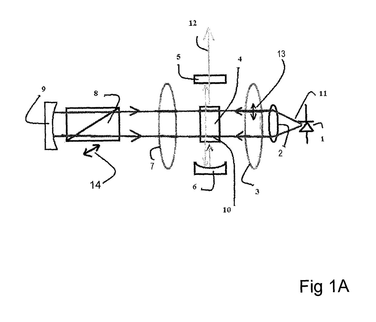
[0040]Embodiments of the present invention are exhibited in the components shown in FIG. 1A. The ECLD 1 in this embodiment was obtained from AXCEL Corporation. The peak wavelength of the gain spectrum is 780 nm+ / −2 nm, and has front facet an...


PUM


Abstract

A laser using a laser diode and a narrow wavelength from a resonant atomic transition of a predetermined material. The gain range of the laser diode encompasses the wavelength of the resonant atomic transition. A vapor cell containing a material, such as a metal vapor, providing the resonant atomic transition forming the predetermined wavelength is placed between permanent magnets. In one embodiment the vapor cell has opposing windows positioned at a Brewster's angle and rotated 90.degree. relative to each other. The laser produces a very narrow bandwidth of a predetermined wavelength with high power. The laser configuration eliminates several optical components reducing cost.

Description

RELATED APPLICATION[0001]This application claims the benefit of U.S. Provisional Application No. 62 / 182,812 filed Jun. 22, 2015, which is herein incorporated by reference.FIELD OF THE INVENTION[0002]The invention relates in general to intracavity atomic vapor lasers operating on resonant atomic transitions using an External Cavity Laser Diode (ECLD) and more particularly to improving the efficiency, temperature independence, and wavelength narrowing and accuracy of a beam with a minimum of optical elements.BACKGROUND OF THE INVENTION[0003]A class of diode pumped alkali vapor lasers (DPAL) demonstrated by Krupke, in U.S. Pat. Nos. 6,643,311 and 7,061,958 B2 requires resonantly matched optical pumps with a spectral width greater than 10 picometers and wavelength corresponding to the D2 transition. The D2 transition occurs between the ground 2S1 / 2 state and the excited 2P3 / 2 state. The DPAL is pumped by bleaching to the D2 transition and simultaneously shifting the population of the 2P...

Claims


Application Information

Patent Timeline
IPC IPC(8): H01S3/08H01S3/0941H01S5/14H01S5/40H01S3/227H01S3/106H01S3/10
CPCH01S3/1066H01S5/14H01S3/0941H01S3/227H01S3/08054H01S5/4087H01S3/07H01S3/08027H01S3/08031H01S3/102H01S5/141
Inventor SOBCZYNSKI, RADOSLAW M.
Owner SOBCZYNSKI RADOSLAW M
Learn More