Numerical control system having synchronous control function between units

a technology of synchronous control and control function, applied in the field of numerical control system, can solve the problems of inability to correctly perform synchronous control and invite degradation of synchronization accuracy, and achieve the effect of maintaining synchronization accuracy

Active Publication Date: 2019-03-05
FANUC LTD
View PDF18 Cites 0 Cited by
  • Summary
  • Abstract
  • Description
  • Claims
  • Application Information

AI Technical Summary

Benefits of technology

[0008]An object of the present invention is to provide a numerical control system in which a numerical controller to be a master unit and a numerical controller to be a slave unit perform synchronous control of axes controlled by each numerical controller, wherein synchronization accuracy is maintained even if retransmission of transfer occurs.
[0013]According to a numerical control system in the present invention, synchronization accuracy can be maintained by correcting a delay due to retransmission of transfer data. Also, when the master unit and the slave unit are connected via a repeater or the like, even if data transfer is delayed in accordance with operating conditions of the repeater in some cases, synchronization accuracy can be maintained by correcting the delay.

Problems solved by technology

Thus, if clocks are not set among a plurality of numerical controllers for which the synchronous control is performed, the master unit and the slave unit have different time information and cannot correctly perform synchronous control.
If a transfer error occurs under the influence of, for example, noise in the data transfer for synchronization between the master unit and the slave unit, data is retransmitted, but if data is retransmitted, transfer data may not be transferred at regular intervals so that the time interval between the determined timing for the master unit to transfer and the reception of data by the slave unit increases.
Then, the slave unit cannot detect a lag of the time information between the master unit and the slave unit and makes corrections based on the erroneous time information and therefore, the slave unit cannot correctly correct control information of the master axis and as a result, causes a synchronization error, posing a problem of inviting degradation of synchronization accuracy.

Method used


Image

  • Numerical control system having synchronous control function between units
  • Numerical control system having synchronous control function between units
  • Numerical control system having synchronous control function between units

Examples


Embodiment Construction

[0023]First, before illustrating the operation principle of the present invention, the synchronous control system described in Japanese Patent Application Laid-Open No. 2007-89331 as the prior art described above will be described.

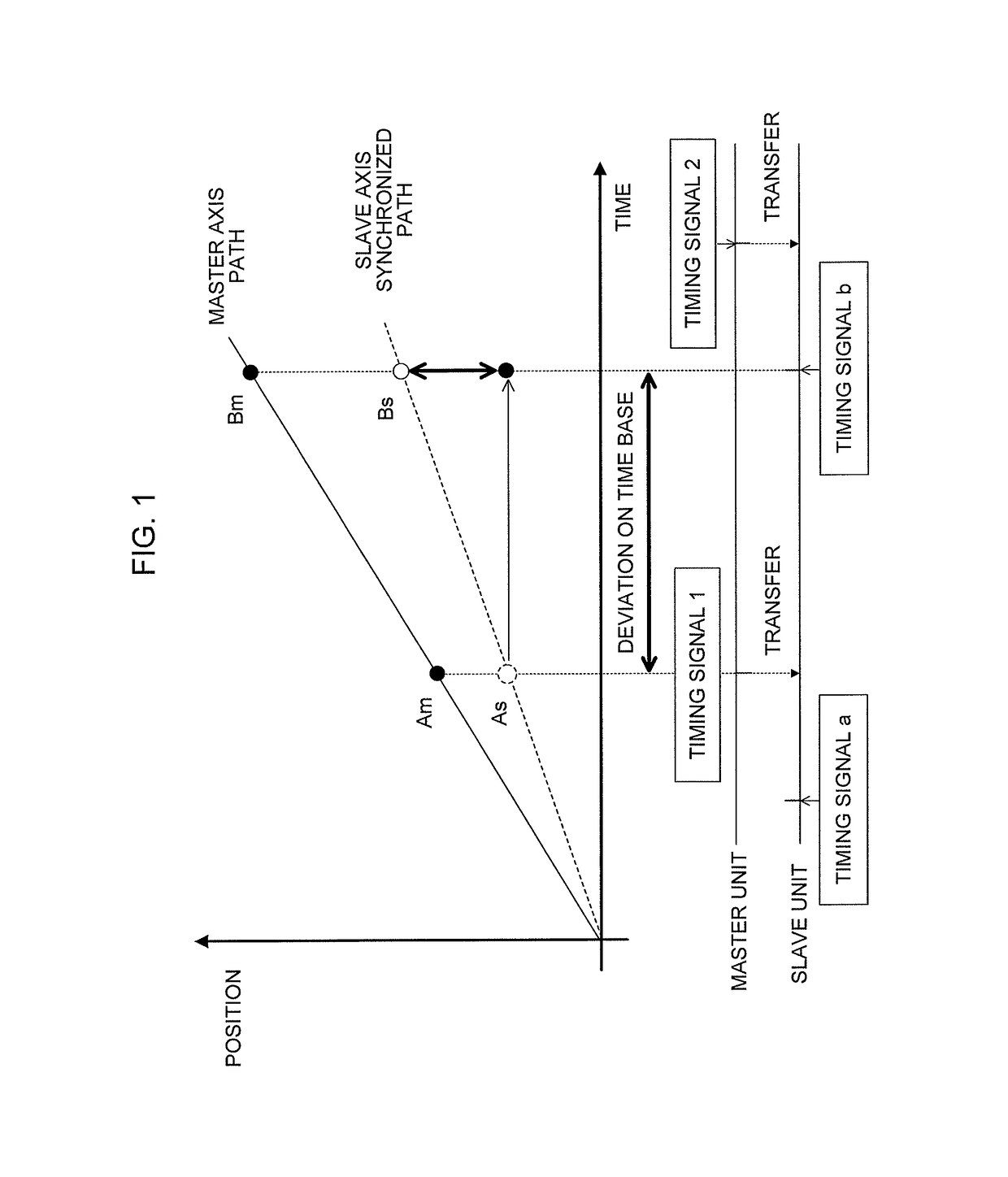
[0024]The synchronous control system includes a controller to be a master unit and a controller to be a slave unit, each of the master unit and the slave unit periodically generates a timing signal, and synchronous control is performed by transferring the position of the master axis to the slave axis based on the timing signal of the master unit.

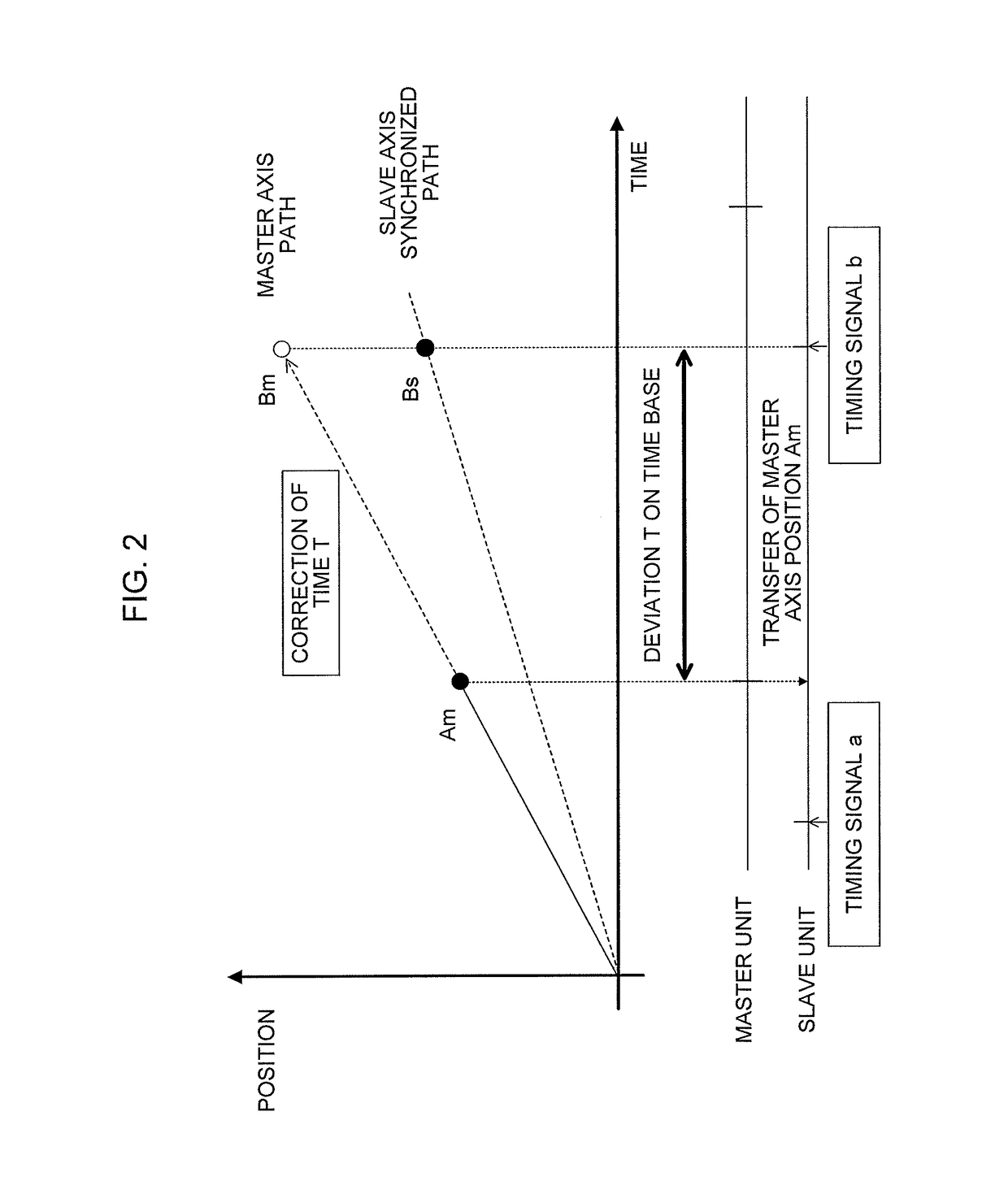
[0025]In the synchronous control system as described above, the slave unit receives information of the position of the master axis and acquires the time elapsed from the timing signal of the slave unit as the reception time thereof. Then, the position of the master axis and the reception time are recorded. The master unit and the slave unit have timing signals generated in the respective units and control the axes ...


PUM


Abstract

A master unit that controls a master axis and a slave unit that controls a slave axis are connected via a communication path to construct a numerical control system. The slave unit acquires a reception time of synchronization information received from the master unit and records a history of the reception time of the synchronization information. Then, when retransmission of transfer of the synchronization information is detected, the slave unit corrects the reception time of the synchronization information based on history data of the reception time and corrects asynchronous position of the slave axis based on a corrected reception time.

Description

BACKGROUND OF THE INVENTION[0001]1. Field of the Invention[0002]The present invention relates to a numerical control system, and in particular, relates to a numerical control system capable of maintaining synchronization accuracy in synchronous control between numerical controllers.[0003]2. Description of the Related Art[0004]If, in a machine in which many axes need to be synchronized such as a printing machine, the number of axes to be synchronized is not sufficient for the number of control axes of one numerical controller, two or more numerical controllers are connected by a communication path and axes to be controlled of each numerical controller are synchronized. When synchronous control of a plurality of numerical controllers is performed in such a synchronous control system, axes in a synchronous relationship are each set as a master axis and a slave axis, a numerical controller to control an axis to be a master axis is called a master unit, a numerical controller to control ...

Claims


Application Information

Patent Timeline
Patent Type & Authority Patents(United States)
IPC IPC(8): G05B19/414
CPCG05B19/4141G05B2219/34015G05B2219/33342G05B2219/33215G05B19/18
Inventor HORIGUCHI, KOUICHIROU
Owner FANUC LTD
Why Eureka
Try Eureka