
A synchronous hydraulic system and crane

A hydraulic system and synchronous component technology, applied in the hydraulic field, can solve problems such as out-of-control synchronous movement of two cylinders, increased cost, and reduced system reliability, and achieve the effects of avoiding large overshoot, reducing design cost, and good reliability

Active Publication Date: 2018-04-17
ZHUZHOU TIANQIAO CRANE
View PDF7 Cites 0 Cited by
  • Summary
  • Abstract
  • Description
  • Claims
  • Application Information

AI Technical Summary

Problems solved by technology

The traditional open-loop hydraulic synchronous circuit cannot meet the occasions with high requirements for synchronous precision
[0004] If the common closed-loop method of proportional reversing valve or proportional speed regulating valve is connected in series on the main oil lines of the two oil cylinders, a large-diameter valve must be selected, which will greatly increase the cost. Problems such as low process synchronization accuracy
In addition, the proportional directional valve has poor pollution resistance. If the proportional directional valve does not work properly due to pollution or electronic control, it will cause the synchronous motion of the two cylinders to be completely out of control, and the system reliability will be reduced.

Method used


Image

  • A synchronous hydraulic system and crane
  • A synchronous hydraulic system and crane

Examples


Embodiment 1

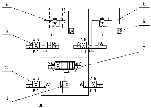
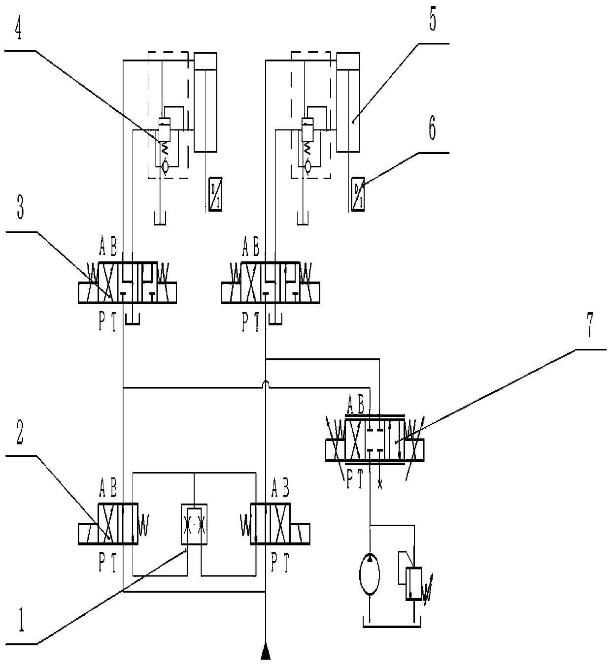
[0030] This embodiment provides a synchronous hydraulic system, including an oil pump, a control element, a first actuator, and a second actuator; the control element includes a primary control element for coarse flow adjustment and a secondary control element for fine flow adjustment ; The primary control element includes a first reversing valve, a second reversing valve, and a flow-dividing and converging valve; the secondary control element includes a third reversing valve, a fourth reversing valve, and a proportional reversing valve; The two working oil ports of the valve are respectively connected in parallel with the oil inlet ports of the third reversing valve and the fourth reversing valve;

[0031] The primary control element is connected with the oil pump; the oil outlet of the oil pump is selectively communicated with the oil inlet of the synchronous element or the oil inlet of the third directional valve through the first reversing valve; the oil outlet of the oil p...

Embodiment 2

[0050] The difference between embodiment 2 and embodiment 1 lies in the connection mode of the two proportional reversing valves 7 and the difference of the synchronous components. Such as figure 2 As shown, the working oil port of proportional reversing valve 7 is respectively connected with the oil inlet port of the third reversing valve and the oil inlet port of the fourth reversing valve, the oil port T is cut off, and the oil port P is connected to the charge pump; in this embodiment The middle synchronous element is a synchronous motor (not shown in the figure).

[0051] When performing synchronous control of oil cylinders, the difference between this embodiment and Embodiment 1 lies in the fine adjustment method of the secondary flow rate, and this embodiment compensates the synchronization error by means of oil replenishment.

[0052] In the following, when the two oil cylinders are lowered, the speed of the first oil cylinder is slightly faster as an example to illu...


PUM


Abstract

The invention relates to the technical field of hydraulic control, and discloses a synchronous hydraulic system and a crane. The synchronous hydraulic system comprises an oil pump, a control component, a first execute component and a second execute component. The control component comprises a primary control component and a secondary control component. The primary control component is used for roughly adjusting the flow. The secondary control component is used for finely adjusting the flow. The primary control component comprises a first reversing valve, a second reversing valve and a synchronization component. The secondary control component comprises a third reversing valve, a fourth reversing valve and a proportional reversing valve. The two-stage synchronization principle is adopted, the adjusting precision is high, the reliability is high, and besides, selection of large-diameter proportional reversing valves is avoided, and the cost is reduced.

Description

technical field [0001] The invention relates to the field of hydraulic technology, in particular to a synchronous hydraulic system and a crane. Background technique [0002] With the continuous development of large-capacity prebaked electrolytic cell technology in the aluminum industry, in order to improve production efficiency and reduce production costs, aluminum enterprises require aluminum electrolysis multi-functional cranes to have more complete functions. The improvement. The anode replacement mechanism is the main operating mechanism of the central feeding prebaking electrolytic cell. In order to improve the efficiency of anode replacement, the new aluminum electrolysis multifunctional unit adopts a double anode replacement method. Due to the long stroke of the double oil cylinder of the anode replacement mechanism, the excessive synchronization error in the field work often leads to the falling of the covering material between the two anodes, which not only pollute...

Claims


Application Information

Patent Timeline
Patent Type & Authority Patents(China)
IPC IPC(8): F15B11/22F15B13/06B66C13/20
CPCB66C13/20F15B11/22F15B13/06F15B2211/205F15B2211/782
Inventor 唐海斌谭永新罗敏郑正国吕方
Owner ZHUZHOU TIANQIAO CRANE
Learn More