Permanent magnet motor

a permanent magnet motor and magnet technology, applied in the direction of dynamo-electric machines, magnetic circuit rotating parts, magnetic circuit shape/form/construction, etc., can solve the problems of limited use of motors, lack of optimized detailed technical content, etc., to reduce vibration and noise, improve control precision, and reduce cogging torque

Active Publication Date: 2019-02-19
HIWIN MIKROSYST
View PDF45 Cites 2 Cited by
  • Summary
  • Abstract
  • Description
  • Claims
  • Application Information

AI Technical Summary

Benefits of technology

[0007]Accordingly, the main objective of the present invention is to provide a permanent magnet motor, in which holes disposed in a magnetic island of a rotor of a motor are optimized in configuration of the shape, the diameter and the spatial form, thereby reducing a cogging torque, a total harmonic distortion of a counter electromotive force, and a torque ripple, and further improving control precision and reducing vibration and noise.

Problems solved by technology

Cogging of a motor affects performance and also produces vibration and noise, causing restriction and inconvenience in use of the motor.
Although such conventional art discloses hole constructions to change flux distribution of a rotor core, the prior art lacks optimized detailed technical content such as the shape, the number, the size and the position of the holes for the efficacy of reducing the cogging torque.

Method used


Image

  • Permanent magnet motor
  • Permanent magnet motor
  • Permanent magnet motor

Examples


Embodiment Construction

[0038]Descriptions are made step by step with reference to an embodiment of the present invention in combination with drawings.

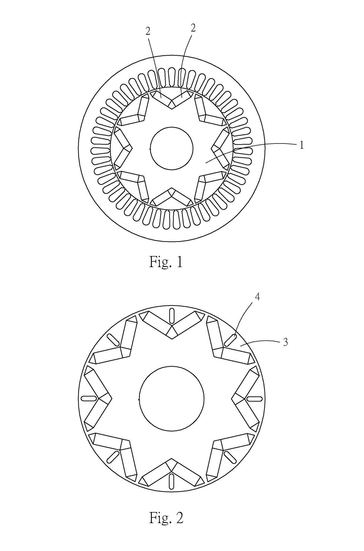
[0039]First, referring to FIG. 3 and FIG. 4, a permanent magnet motor (10) provided in the embodiment of the present invention mainly includes a stator (20), a rotor (30), an air gap (40), a plurality of magnets (50), and a plurality of holes (60).

[0040]The stator (20) is a tubular body having an appropriate wall thickness.

[0041]The rotor (30) is cylindrically and coaxially fitted in the stator (20).

[0042]The air gap (40) is annular and between an outer peripheral annular surface of the rotor (30) and an inner peripheral annular surface of the stator (20), so that the inner peripheral annular surface of the stator (20) is spaced apart from the outer peripheral annular surface of the rotor (30) without direct contact.

[0043]The magnets (50) are pairwise buried in a V shape in the rotor (30) with a V-shaped convergent end facing toward a center of the rotor (30...


PUM


Abstract

The present invention provides a permanent magnet motor, in which three holes, including a middle hole and side holes located on two sides of the middle hole, are disposed in a magnetic island of a rotor, the middle hole and the side holes satisfying specific conditions respectively, thereby achieving an optimal cogging reduction efficacy.

Description

BACKGROUND OF THE INVENTION[0001]1. Field of the Invention[0002]The present invention relates to a permanent magnet motor, and more particularly to a permanent magnet motor with lower cogging torque.[0003]2. Description of the Related Art[0004]Cogging of a motor affects performance and also produces vibration and noise, causing restriction and inconvenience in use of the motor. Therefore, the conventional art is all devoted to the research and development of reduction on a cogging torque of a motor, and the prior art intending to reduce cogging by technical means such as a shape, a size, a pole pitch and a magnetization mode of a magnet, an opening angle of magnets, a depth of a boot, a combination of the number of slots / poles, and an auxiliary slot is disclosed.[0005]Specifically, the prior art shown in FIG. 1 discloses a built-in construction that achieves the efficacy of reducing cogging by changing an opening angle of a pair of magnets (2) of a rotor (1), in which the pair of ma...

Claims


Application Information

Patent Timeline
Patent Type & Authority Patents(United States)
IPC IPC(8): H02K1/27H02K1/02
CPCH02K1/2766H02K1/02H02K2213/03H02K1/2733H02K1/2753H02K1/27
Inventor KUO, JHEN NANZHENG, LI-WEIHSIEH, MING HUNG
Owner HIWIN MIKROSYST
Why Eureka
Try Eureka